© 2020 Thorlabs GmbH
6 Appendix
69
6.3 Interlock Circuit
Interlock
The hardware interlock is a safety feature, accessible via the INT LOCK connector (3) on the
rear panel. By default, a short circuit jumper is installed to the jack.
The interlock interface represents a current source (~1 mA when the LED is switched on),
where the voltage across the external circuit is observed. As soon as this voltage rises above
the TTL H Level, the external circuit is considered "open" and the LED current output is dis-
abled.
Instead of the jumper, an external emergency switch (opener) can be connected to the inter-
lock, as well as an external circuit (total resistance < 1 kW).
6.4 Connect a Custom LED
You can connect a custom LED to your DC2200 using the supplied connection cables.
Custom High Power LED (up to 10 A - Terminal LED1)
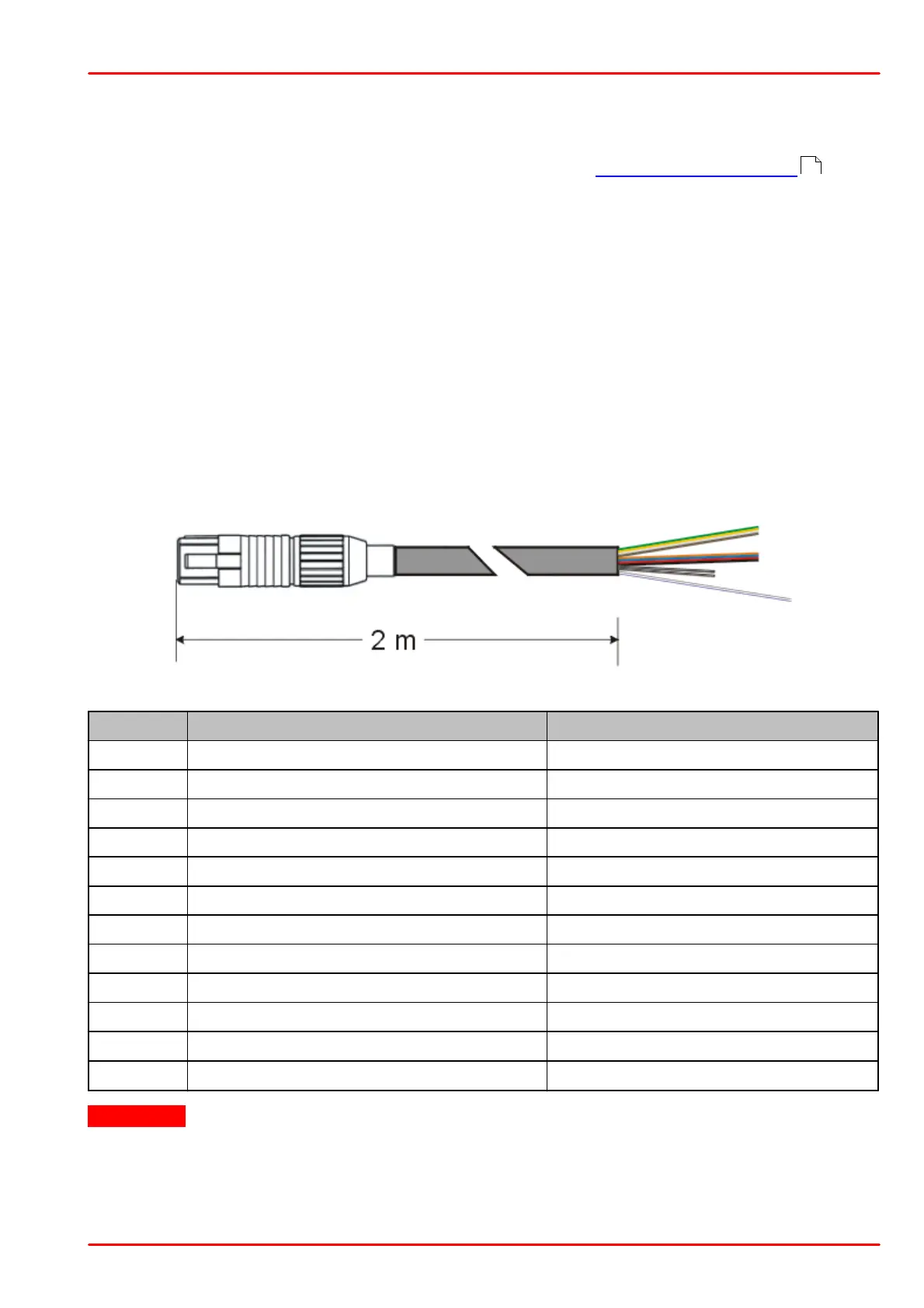
Use the supplied cable CAB-DC2200:
Connection scheme:
6 V - 13 V power supply for fan
Ground power supply for fan
Attention!
Do NOT connect anything to the bi-color wires (white / black and white / brown striped)! The
DC2200 might be damaged!
8