368 DCx camera
© 2010 Thorlabs
9
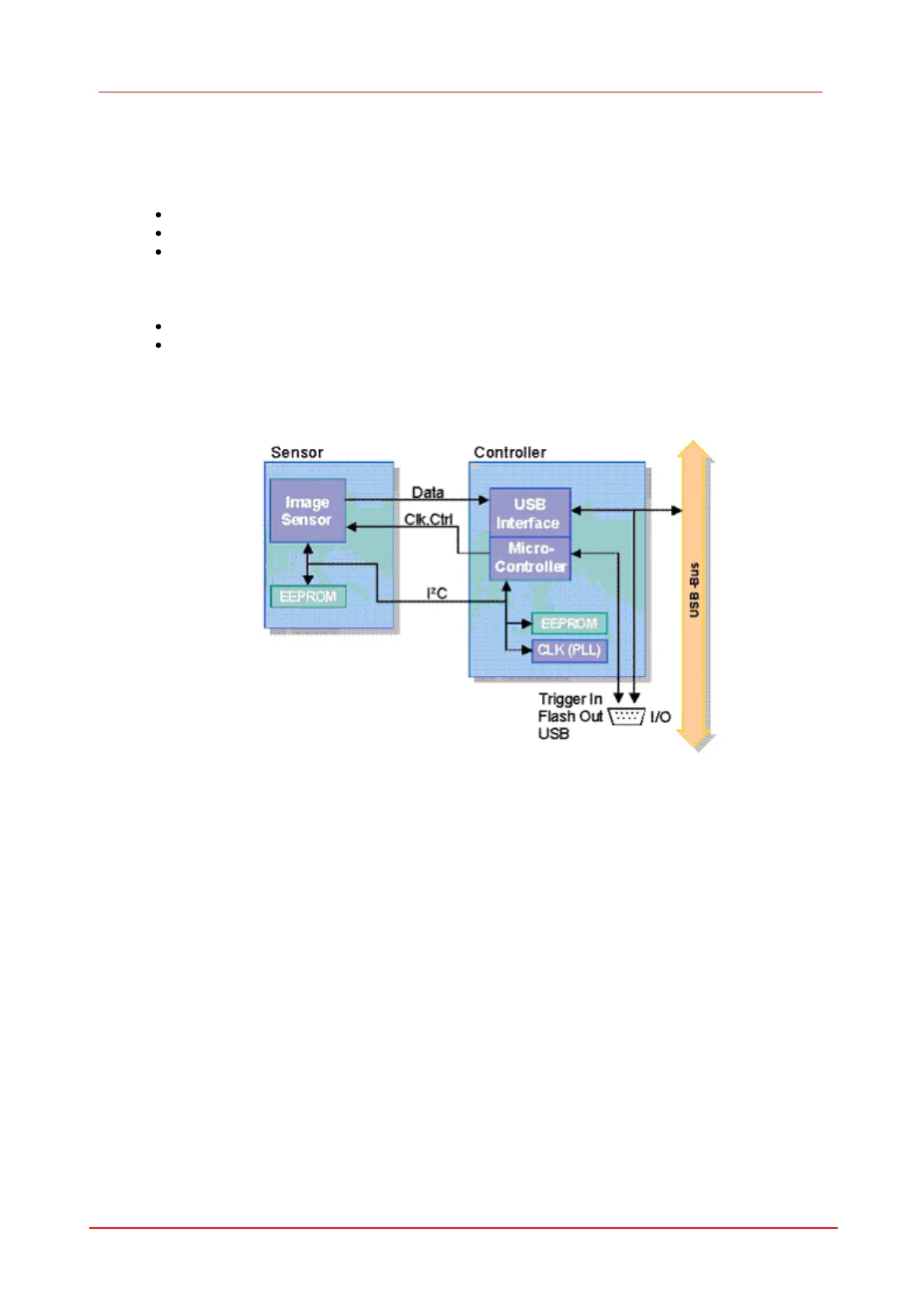
Camera Basics
DCU camera has a modular structure consisting of the following components:
USB board. This includes:
an USB2.0 interface which controls data transmission between camera and host PC
a micro-controller for trigger and flash signals, pixel clock and image size
an EEPROM where the cameras vendor, type and serial number are stored and a memory area of
64 bytes which can freely be used by the use.
Sensor board. This board includes
The sensor.
An EEPROM where the type of camera is stored.
Timing board
The timing board digitises the output signals of the sensor.
Figure 61 Block diagram of the DCU camera
 Loading...