© 2007-2012 Thorlabs GmbH
130 WFS Series
6.3.4
Trigger Input WFS
Trigger Input Specifications
AttentionAttention
Do not apply voltages exceeding the given specifications,
you may damage the WFS instrument!
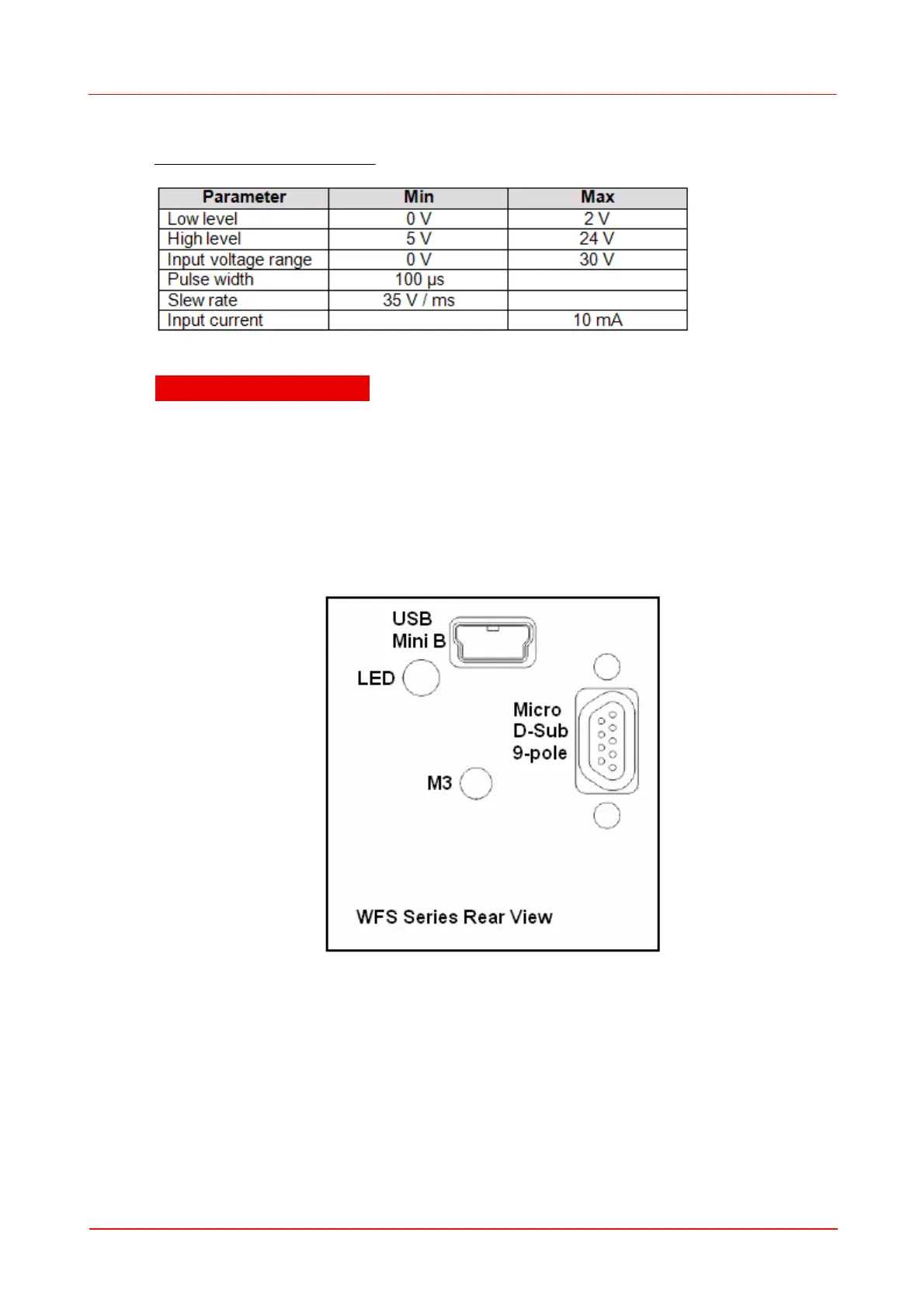
The trigger input of the WFS series instruments is placed at the rear side of the
camera housing. Besides the standard USB Mini B connector which is normally
used to connect the WFS to a PC a second 9-pole Micro D-Sub connector is
available for trigger input.
Note: For using the trigger input you need to replace the standard USB cable
supplied with the WFS instrument with the optionally available combined USB /
Trigger Cable CAB-DCU-T2 which needs to be connected to the Micro D-Sub
jack.
 Loading...