© 2007-2012 Thorlabs GmbH
31Operating Instruction
and to allow for the mounting of additional optical components.
Beam Size
The active area on the CCD / CMOS camera chip can be selected (see Camera
Settings Setup ) in order to adapt it to the actual beam size. Otherwise, a beam
much smaller than the sensor area will illuminate only the microlenses at the center
and no wavefront data can be retrieved from the ambient area. Also the
measurement speed is increased when the camera image size is reduced to fit the
real beam diameter.
A beam size larger than the available aperture (5,95 x 4,76 mm for WFS and 6,33 x
4,75 mm for WFS10) can be adapted using beam expanders (Thorlabs BE01 -
BE20 series).
Beam Alignment
Align the Wavefront Sensor so that the beam to be analyzed launches the instrument
perpendicular to its front face. In some cases a small tilt angle out of that position
can be helpful to prevent unwanted back reflection into the measurement setup.
Direct the beam to be analyzed into the center of the entrance aperture of the
Wavefront Sensor. Although an off-center beam can also be measured as long as it
is not truncated by the active sensor area it is recommended to adjust the beam to
be measured so that it hits the center of the Wavefront Sensor. Verify this adjustment
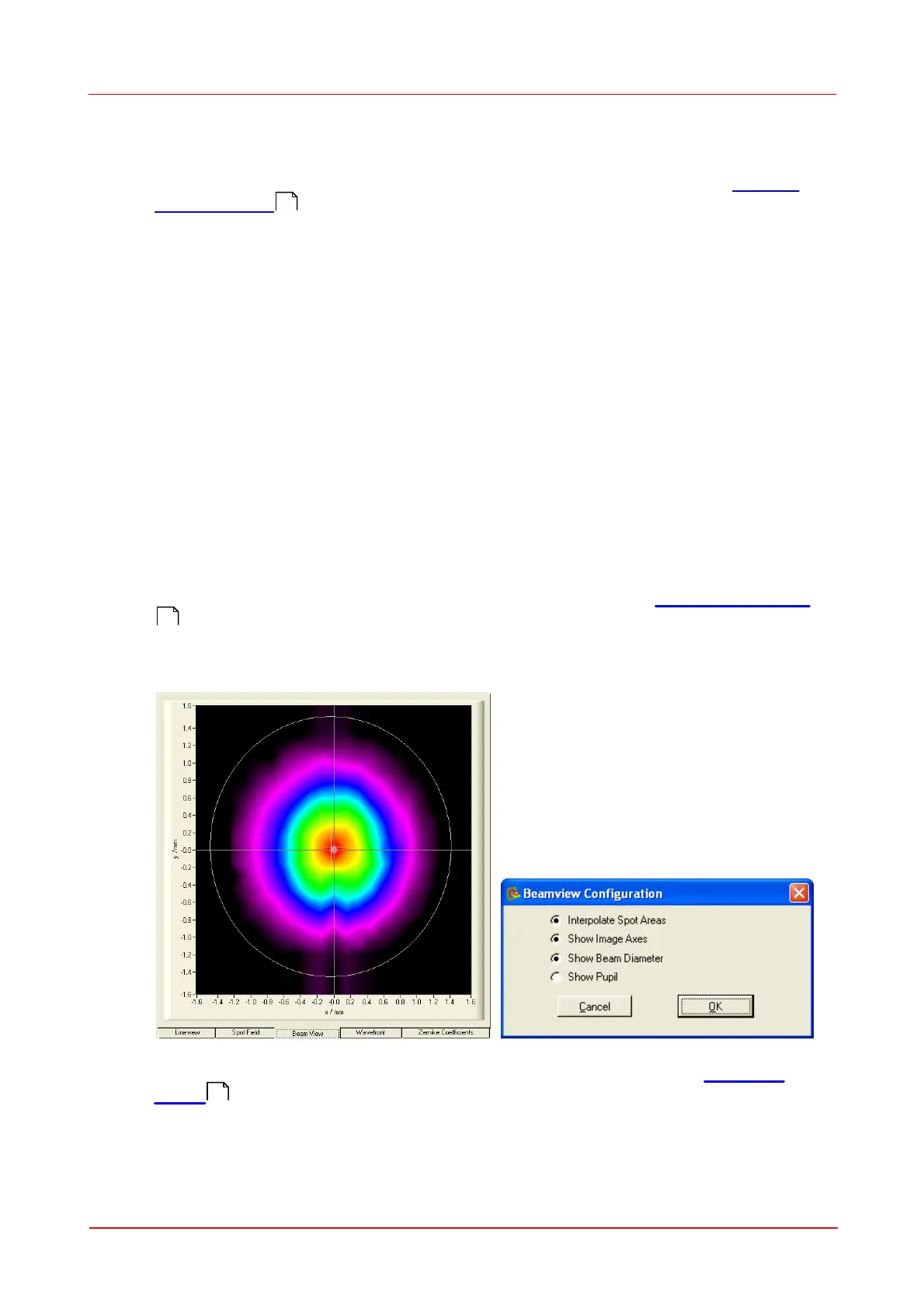
by checking the power density distribution displayed within the Beam View Panel
. Enable the Beam View options 'Show Image Axes' and 'Show Beam
Diameter' in order to visualize the beam position and size with respect to the
analyzed sensor area.
Alternatively, you can check the correct beam position also using the Spotfield
Panel . Enable the diagram options 'Show Image Axes' and 'Show Pupil'.
6
7
56
52
 Loading...