© 2007-2012 Thorlabs GmbH
68 WFS Series
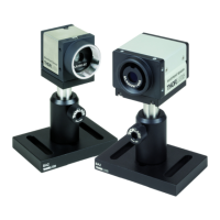
electrical input and no wavefront measurement and screen update take place. This
state is indicated by the 'Awaiting hardware trigger...' message within the Status/
Error window at the bottom.
In addition, a trigger delay can be programmed in the range 15 µs to 4 s.
After the trigger edge was detected by the WFS camera it waits the specified time
interval until it starts exposure of the next image.
Camera Image Size defines the active area of the camera used for measuring the
wavefront. This setting should be adapted to the beam size applied to the
instrument. Limiting the used camera size will reduce the unused sensor area and
increases measurement speed because of saving time for evaluating the spotfield
images.
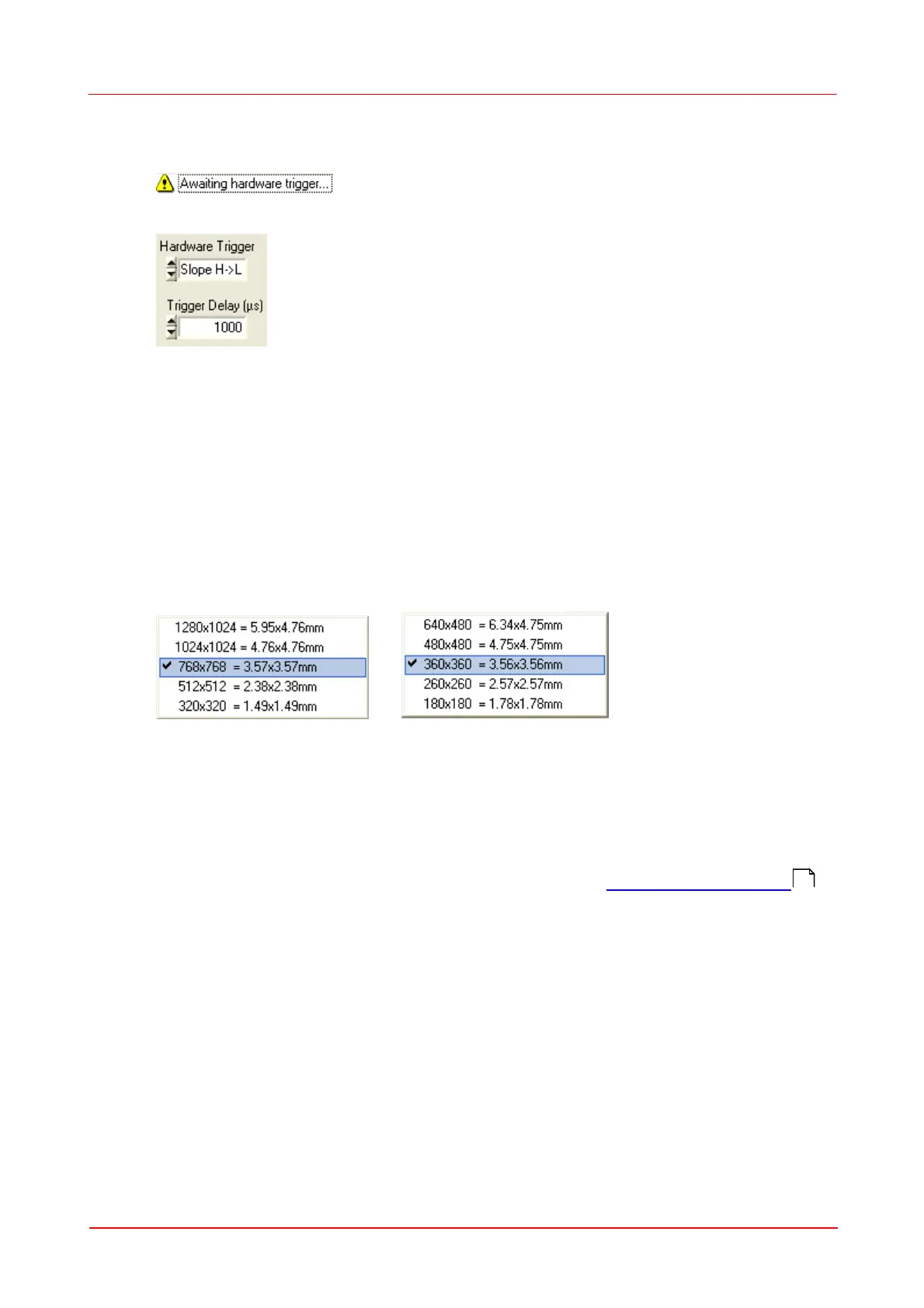
The following area sizes can be selected for WFS (left) and WFS10 (right),
respectively:
The WFS CCD camera offers a maximum of 1280 x 1024 pixel = 1.3 MegaPixel on
a rectangular area 5.95 x 4.76 mm while the WFS10 CMOS camera offers a
maximum of 640 x 480 pixel = 0.3 MegaPixel on a rectangular area 6.34 x 4.75 mm.
For beams that have a larger diameter than 4.7 mm, only a fraction of the beam
cross section can be analyzed by the instrument. The Wavefront Sensor is 'over
filled' regarding the entrance aperture but can still yield correct results. In this case
special care must be taken to the pupil parameters (see Pupil Definitions Setup ).
The following graph illustrates the selectable image sizes for WFS and WFS10
instruments.
7
6
 Loading...