© 2007-2012 Thorlabs GmbH
90 WFS Series
point source is located in front of the Wavefront Sensor reference plane whereas
negative values indicate a convergent spherical wavefront which virtual focal point
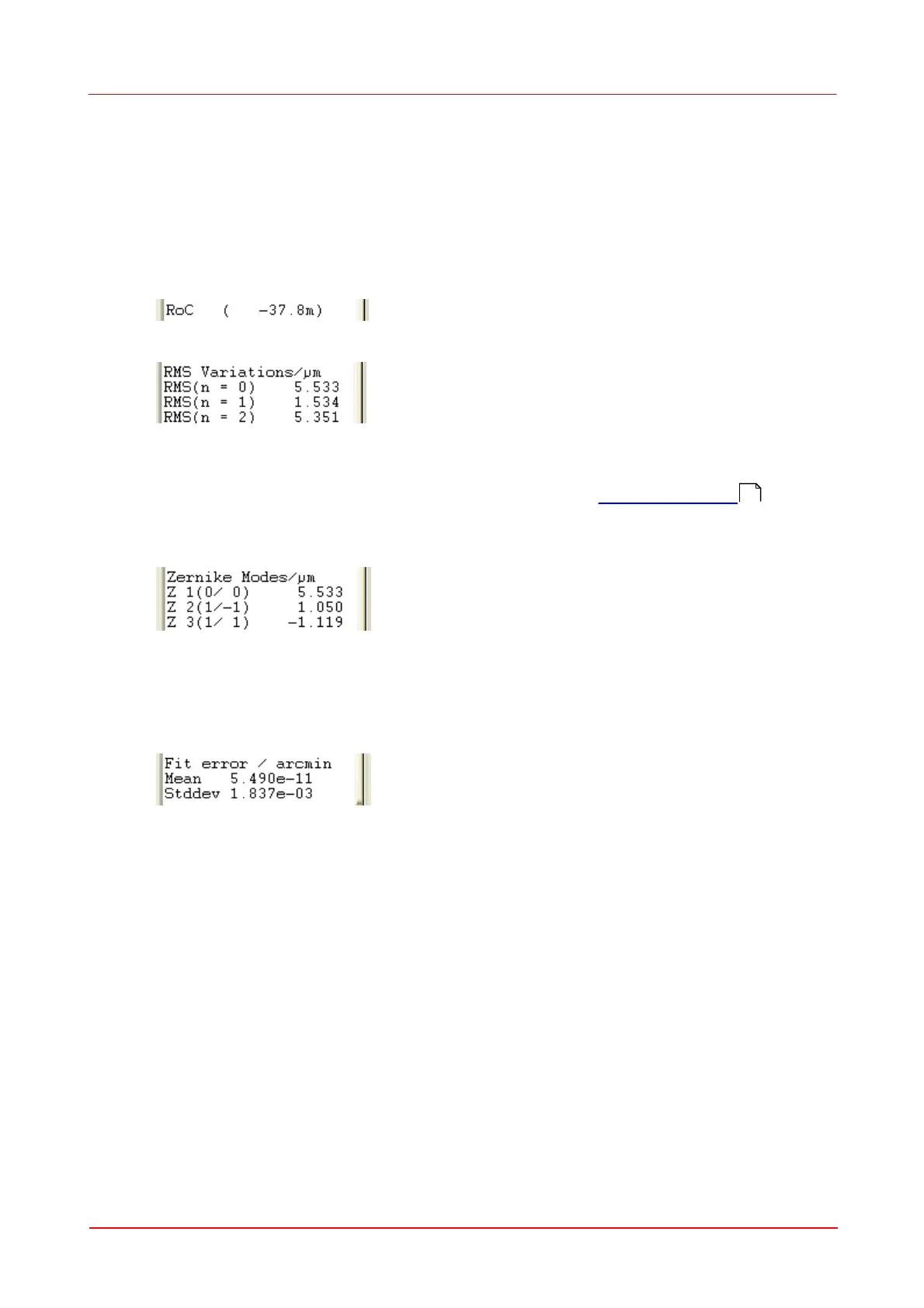
lies behind the Wavefront Sensor reference plane. The higher the absolute RoC
value the more flat is the corresponding wavefront and the higher is the parallelism of
the beam.
In case of a plane wave front, the Z5 term theoretically should be 0, and RoC -
infinite. It's obvious, that the wave front sensor will not be able to measure accurately
large RoC values. In order to point attention to reduced accuracy at RoC values ≥
10.000mm, the result will be displayed like
RMS Variations
Since the Zernike modes are normalized to unity variance, all Zernike coefficients of
a particular order can be summarized and expressed as total RMS variation of this
Zernike order. The number of Zernike orders defined in Zernike Fit Setup panel
will determine the number of output appropriate RMS variation results.
Zernike Modes
The coefficients of the Zernike modes which are determined by a least square fit to
the measured wavefont are either displayed in microns or waves. The mode number
is followed by the order and frequency number of the mode in brackets.
Fit Error
The Fit error describes the difference between the measured and the reconstructed
wavefront. A lower value indicates a better fit. Usually, a Zernike fit using more
modes will reduce the fit error.
8
3
 Loading...