53
NV10P - Manual - 01 - 2015
CHARACTERISTICS
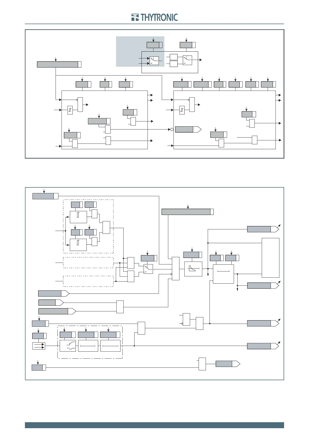
General logic diagram of the undervoltage elements - 27
all-F27.ai
U< Element
U<< Element
MMI
Start U<<
Start U<< Start U<
Trip U<Trip U<<
&
U< disbyU<<
&
U< inhibition
t
U<
def
t
U<
inv
U<
def
t
U<<
def
U<<
def
U<
inv
U< CurveU< EnableState
Block1
BLK1U<
&
U<BLK1
Start U<
&
Block1
BLK1U<<
&
U<<BLK1
Start U<<
&
U<BF
Trip U<
&
U<BF
U<<BF
Trip U<<
&
U<<BF
U
&
U
Disable 27 function by operator
AND
U
12
,U
23
,U
31
U
U
L1
,U
L2
,U
L3
OR
Common configuration
Only with sensor versions
Utype27
Logic27
Logic diagram concerning the first threshold (U<) of the undervoltage element - 27
Fun-F27_S1.ai
U< Inhibition
(ON≡
Inhibit
)
&
U< Curve
0T
RESET
t
U<
0T
TRIPPING MATRIX
(LED+RELAYS)
t
U<def
t
U<inv
Start U<
U<ST-K
Start U<
U<TR-K
U<ST-L
U<TR-L
Trip U<
Trip U<
Trip U<
BF Enable (ON≡Enable)
U<BF
towards BF logic
&
BLK1U<
U< BF
&
&
&
Enable (ON≡Enable)
Block1 input (ON≡Block)
U<BLK1
Block1
Block1
Logic27
≥1
&
U
L1
U
L2
U
L3
Binary input INx
T0
Logic
INx
t
ON
INx
t
ON
INx
t
OFF
T0
n.o.
n.c.
INx
t
OFF
≥1
&
State
U<
inv
U ≤
U<
def
U ≤
U<
inv
U<
def
&
State
ON≡Enable U< undervoltage element
U< Enable
Enable (ON≡Enable)
MMI
Disable 27 function by operator
≥1
(1≡DDI closed)
DDI state
(1≡upstream)
U<disbyCB_OPEN