85
NV10P - Manual - 01 - 2015
CHARACTERISTICS
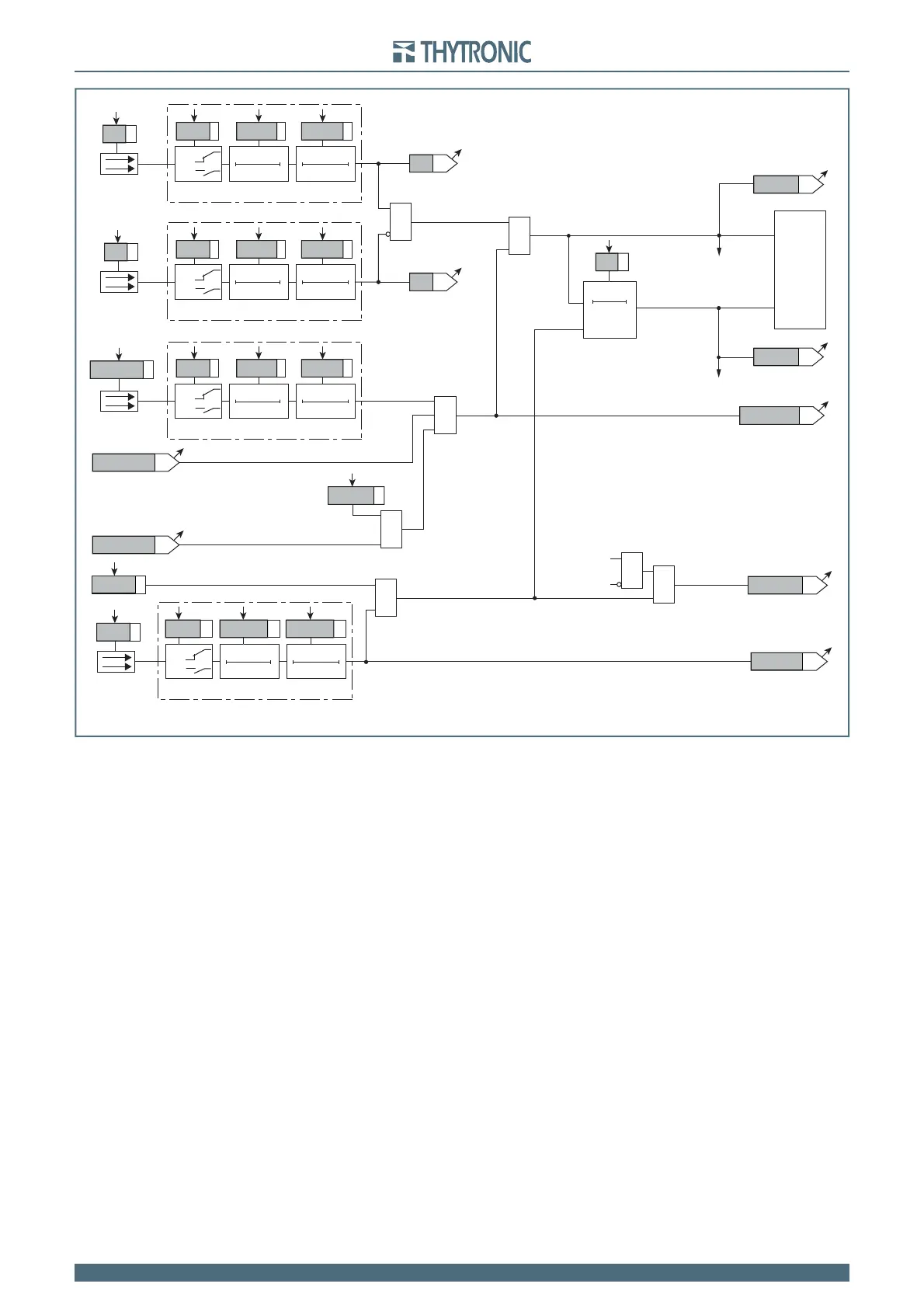
Logic diagram concerning the breaker failure element -BF
Fun-BF_Pro-n.ai
TRIPPING MATRIX
(LED+RELAYS)
Start BF
Trip BF
Trip int-prot
&
&
Block1 input (ON≡Block)
BLK1 BF
Trip Int/Ext
Block1
ON≡
CB Closed
Start BF
Start BF
Trip BF
Trip BF
Trip ProtExt
52a
&
Block1 enable (ON≡Enable)
Trip of enabled protective elements (ON≡Trip)
BF-BLK1
Block1
52a
RESET
tBF
0T
t
BF
RemTrBF
≥1
&
&
&
Remote trip
Remote trip (ON≡Remote trip)
Binary input INx (x=1...8-16)
T0
Logic
INx
t
ON
INx
t
ON
INx
t
OFF
T0
n.o.
n.c.
INx
t
OFF
Binary input INx
T0
Logic
INx
t
ON
INx
t
ON
INx
t
OFF
T0
n.o.
n.c.
INx
t
OFF
Binary input INx
T0
Logic
INx
t
ON
INx
t
ON
INx
t
OFF
T0
n.o.
n.c.
INx
t
OFF
Binary input INx
T0
Logic
INx
t
ON
INx
t
ON
INx
t
OFF
T0
n.o.
n.c.
INx
t
OFF
52b
52b
BF-ST-K
BF-TR-K
BF-TR-L
BF-ST-L