17
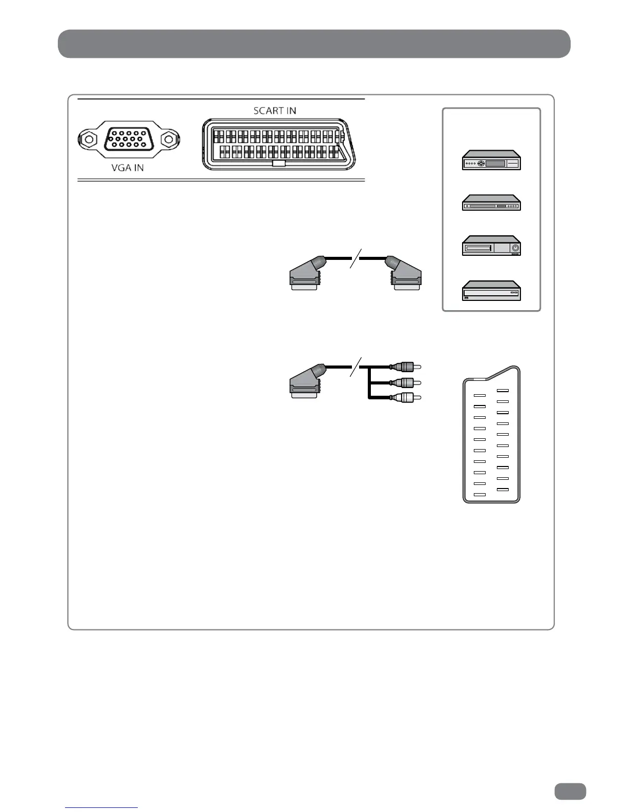
The SCART Connector
All connections must be made before sealing the TileVision
®
into the back box.
The EURO-SCART connector can be used with equipment which has RGB or composite video inputs
and outputs. A VCR, satellite or cable receiver, DVD player, or video game console should be
connected using the EURO-SCART connection.
The EURO-SCART socket is fully wired as shown above.
The audio output from the EURO-SCART can be connected to a separate amplifier to allow
integration with a multi- room audio video system. This should be carried out by a qualified
engineer.
SCART Connection Reference
Pin Name Description
1 AOR Audio Out Right
2 AIR Audio In Right
3 AOL Audio Out Left + Mono
4 AGND Audio Ground
5 BGND RGB Blue Ground
6 AIL Audio In Left + Mono
7 B RGB Blue
8 SWTCH Audio, RGB switch,16:9
9 GGND RGB Green Ground
10 CLKOUT Clock Out
11 G RGB Green
12 DATA Data Out
13 RGND RGB Red Ground
14 DATAGND Data Ground
15 R RGB Red
16 BLNK Blanking Signal
17 VGND Composite Video Ground
18 BLNKGND Blanking Signal Ground
19 VOUT Composite Video Out
20 VIN Composite Video In
21 SHIELD Chassis Ground, Cable Shield
Video Game Console
VCR
DVD Player/Recorder
Satellite Receiver,
Cable Box or Hard Disk
Recorder
19
17
15
13
11
9
7
5
3
1
20
18
16
14
12
10
8
6
4
2
21
(A) SCART to SCART connector
(RGB Video + Audio L/R or
Composite Video + Audio L/R)
(B) SCART to RCA connectors
(Composite Video + Audio L/R)
SCART Pinouts
(solder side view)