Model: CD-36D 2. Names of Major Parts
-
9
-
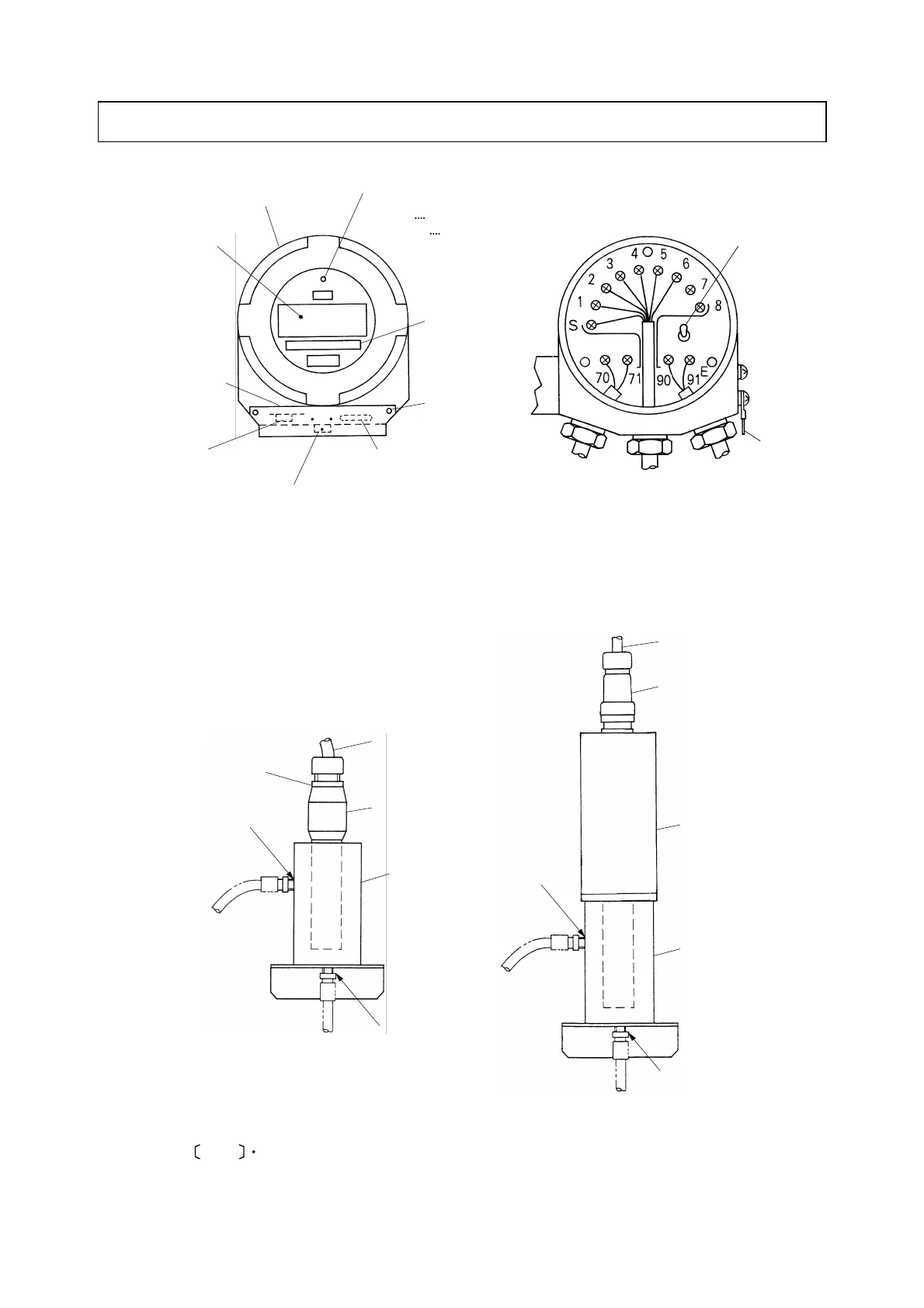
2. Names of Major Parts
Front Cap
Digital Display
Knob Cover:
To prevent knobs
for calibration from
inadvertent touch.
“ZERO Knob:”
For zero adjustment in
calibration
Display of
Measuring
Range
Fixing Screw
for Cover
“SPAN Knob:”
For span adjustment
in calibration
Mode Switch:
To switch the mode to
“MEAS” for “Measurement” mode and
“TEST” for “Maintenance” mode
Cable for
Output Signal
Detector
Lead Wires
Cable for
Power supply
Power Switch
(POWER)
Earth Line
Pilot Lamp:
To display the mode presently set,
If “ON” cin “MEAS” mode
If blinking cin “TEST” mode
Transmitter
Connector
Sample Outlet
Lead Wires
Detector
Flow Cell
(Model: CLZ-1)
Sample Inlet
Sample Outlet
Lead Wires
Detector
Flow Cell
(Model: CLZ-1)
Sample Inlet
Connector
Vibration type residual chlorine detector
CLV Series
Rotation type residual chlorine detector
Model CLR-21-A
NOTE
Flow cell incorporated with an detector is called “Sensor” in this instruction manual.
Sensor