Do you have a question about the TOA-DKK CD-36D and is the answer not in the manual?
Guidance on handling and importance of the instruction manual for safe operation.
Explanation of symbols and markings used for warnings and cautions in the manual and on labels.
Essential safety measures to prevent hazards during product operation and maintenance.
Details of DKK-TOA's warranty for defective material or workmanship during the warranty period.
Exclusions and conditions under which the product warranty does not apply.
Additional information regarding maintenance parts, repair contacts, and warranty service.
Overview of the steps involved in setting up the analyzer for operation, including installation and preparation.
Description of the analyzer's components and how they form a measuring system.
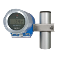
Visual representation and identification of the external parts of the Reagentless Free Chlorine Analyzer.
Step-by-step guide for filling beads into the detector, crucial for its function.
Instructions for filling sodium chloride tablets into the conductivity modifying column (optional).
Procedure for introducing sample water into the sensor, including conditions and flow rate adjustments.
Detailed steps for starting up the analyzer, from power supply to confirmation of measurement readiness.
Procedures for safely stopping the operation of the analyzer and requirements for resuming operation.
Steps for performing zero calibration to ensure accurate baseline readings in maintenance mode.
Procedure for span calibration to adjust the analyzer's output to a known standard value.
Instructions for configuring the analyzer's measurement range using dip-switches.
Method for adjusting the output signal to an arbitrary value during maintenance or calibration.
Overview of regular maintenance and inspection tasks, with recommended intervals and reference sections.
List of consumable and spare parts recommended for yearly stocking and maintenance.
Detailed procedure for cleaning the detector tip and replacing the sensing electrode.
Instructions for replacing the beads in the detector when cleaning performance decreases.
Procedure for cleaning the flow cell to ensure proper sample flow and measurement.
Steps to adjust the output signal to match the displayed value or a specified standard.
Guide for safely replacing a blown fuse in the transmitter.
Information on recommended overhaul intervals for specific detectors and procedures for replacement.
Guidelines for physically mounting the flow cell and detector unit to the system.
Procedures for selecting an appropriate site and mounting the transmitter unit.
Diagram and instructions for connecting the detector, power supply, and output signal.
Details on the optional conductivity modifying column for stable measurement in low conductivity samples.
Specifications and mounting information for the optional CLZ-4 flow cell.
Description of the optional pole stand for mounting the analyzer components.
Key technical specifications of the Reagentless Free Chlorine Analyzer/Transmitter.
Information on the analyzer's performance characteristics like linearity and repeatability.
| Brand | TOA-DKK |
|---|---|
| Model | CD-36D |
| Category | Measuring Instruments |
| Language | English |