Model: CD-36D 8.3 Wiring
-
37
-
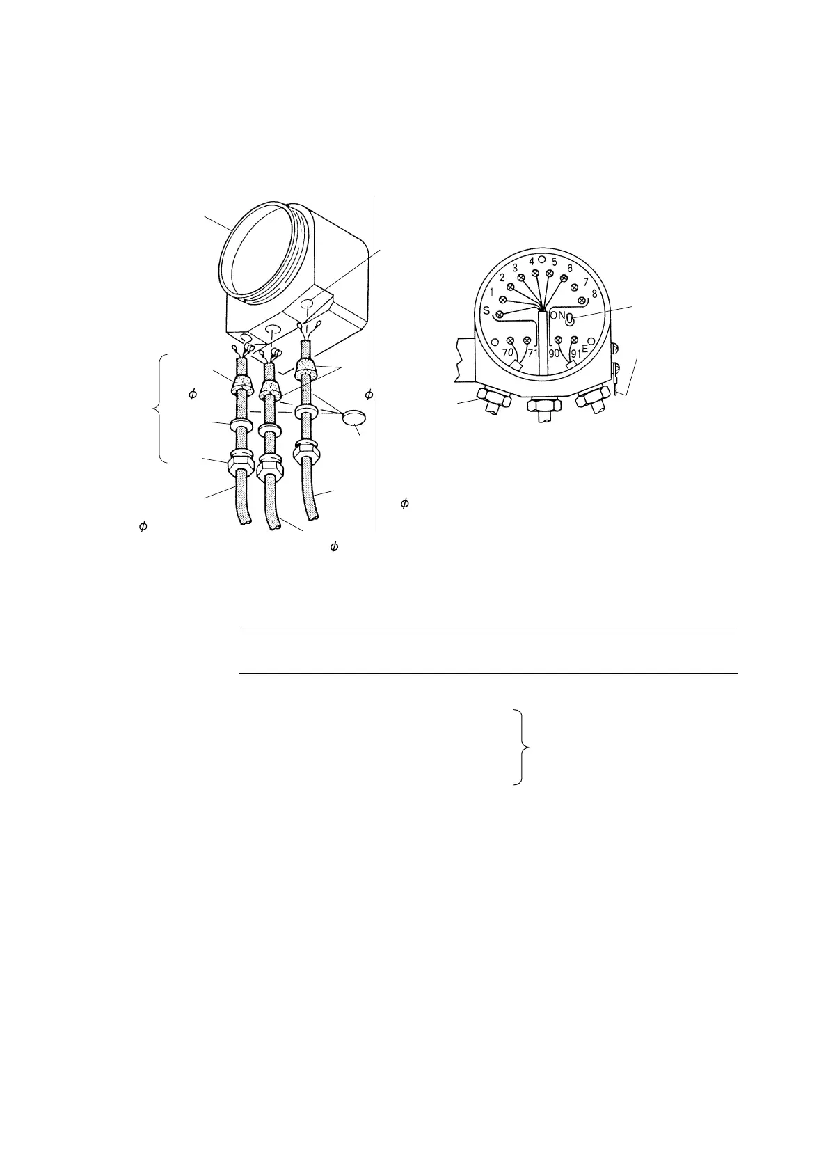
(2) Wiring for the Transmitter
Introduce each cable to the Transmitter and connect terminals of each cable to corresponding
terminals on the terminal board. If the water-seal cable inlet attached to the Transmitter is to be used,
refer to the following figures.
Casing
Cable Inlet
3-G 3/4 (PF 3/4)
< Example of Introduction of Cables >
Washer
Gland
Dust Cover
(To be removed.)
Water-seal
Cable Inlet
Tapered
Packing
(for 8)
Cable for Output
Signal
(OD 8)
Cable for Power
Supply (OD 8)
Tapered
Packing
(for 8)
Power Switch
Water-seal
Cable Inlet
Cable for
Output
Signal
Lead Wires
Cable for
Power
Supply
Earth Line
The threaded hole
on the side of the
casing for fittings
is used.
<Back View of the Transmitter>
Lead Wires
(OD 8)
Wiring for the Transmitter
【IMPORTANT】 • E Make sure not to connect the power supply inadvertently to wrong
terminals other than “90, 91”, which will cause damage to the Transmitter.
〔NOTE〕 • Terminal No. and Wiring:
1, 2·········· Electrode
3, 4·········· Temperature Compensation Element
5, 6·········· Solenoid for Electrode Lead wires
7, 8·········· (Spare)
S ············· Shield
90, 91······ Power Supply
70, 71······ Output Signal
E············· Earth (Usually, the threaded hole on the side of the casing for fittings is used.)