Model: CD-36D 8.3 Wiring
-
36
-
8.3 Wiring
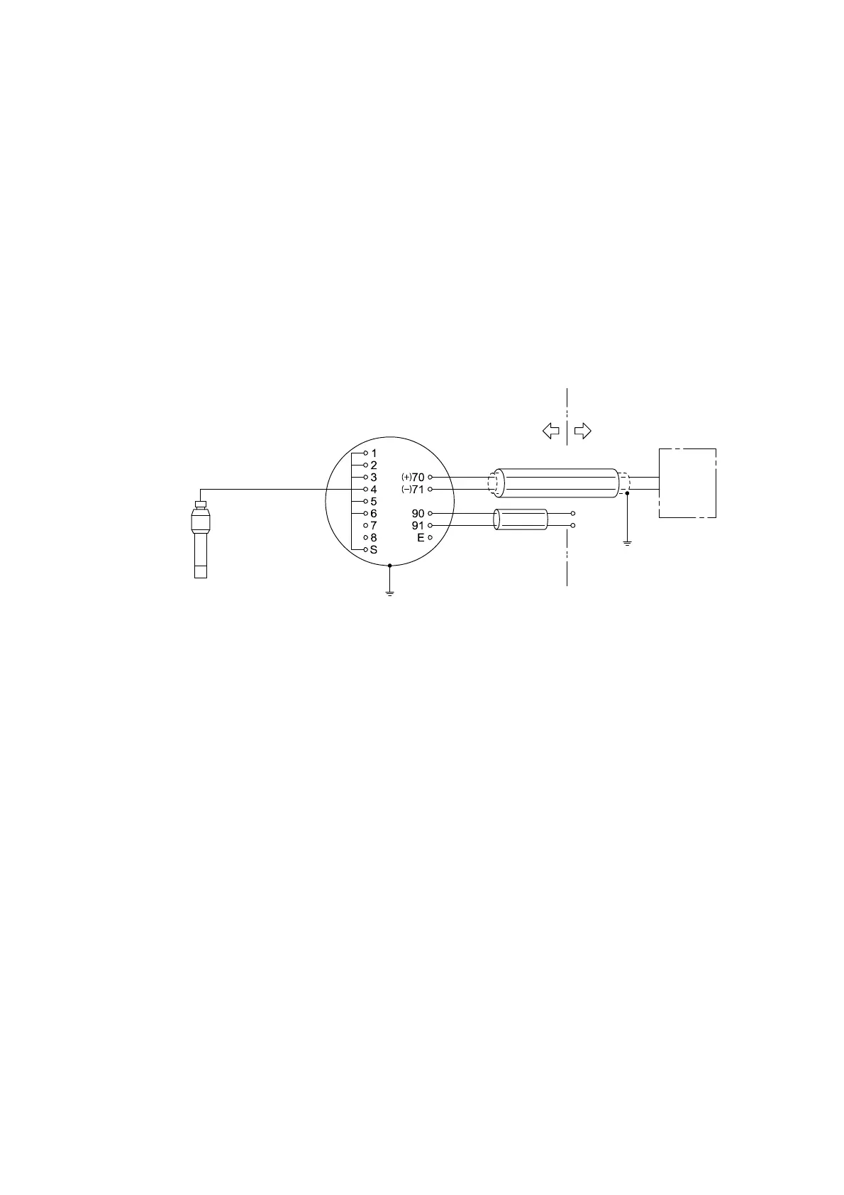
(1) Wiring Diagram
(a) Lead wires ⋅⋅⋅⋅⋅⋅ Connect the lead wires to terminals “1 to 6, S” on the terminal board of the
Transmitter.
(b) Cable for Output Signal ⋅⋅⋅⋅⋅⋅ Connect the Transmitter to a receiver (or a recorder, etc.) with a
shielded 2-core cable (OD φ8mm).
(c) Cable for Power Supply ⋅⋅⋅⋅⋅⋅ Connect the Transmitter to a AC power supply with a 2-core cable for
instrumentation (OD φ8mm). Make sure to minimize the voltage drop to less than 2V.
(d) Ground the “Earth” terminal provided on the casing of the Transmitter to the earth according to the
grounding work of Class-D. (Grounding resistance ≤ 100 Ω)
Lead Wires
Detector
Terminal Board of
the Transmitter
Control
Room
Measurement
Site
Cable for Output Signal
Power
Source
Cable for Power
Supply
Earth Line
Receiver
Wiring Diagram