Model: CD-36D 4.1 Start-up Procedure
-
15
-
Power Switch
(POWER)
Voltmeter
Confirm the line voltage.
Electric Shock
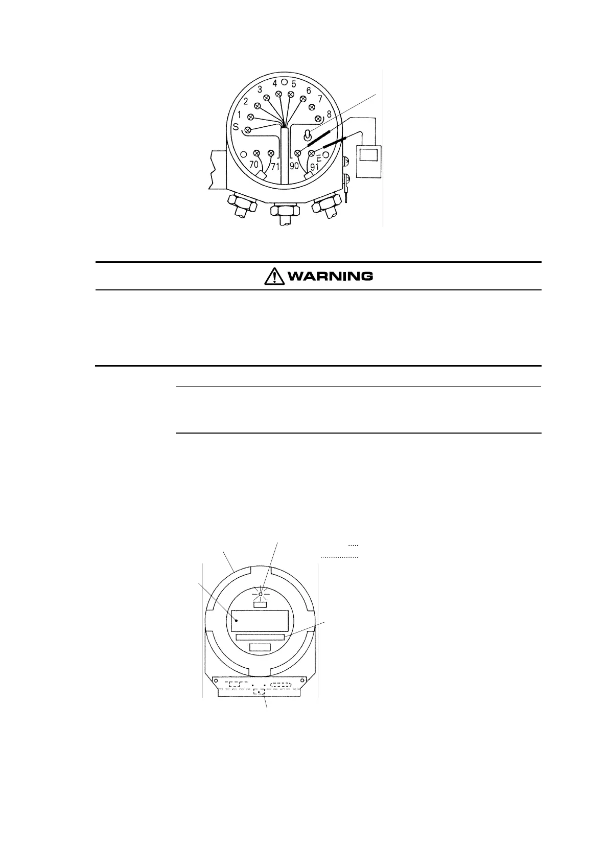
● Since AC power supply is connected to terminals “90, 91”, make sure to turn off the
power supply to the Transmitter on the power supply side in case some work is
needed near the terminal board.
【IMPORTANT】 • Do not turn on the power switch when the flow cell is not filled with sample
water since the sensing electrode may be damaged if it is kept vibrating or
rotating in the air for a long period.
⑤ Confirm that the pilot lamp is blinking. ⋅⋅⋅⋅⋅⋅ Turn on the power switch located on the upper part
of the terminal board, and confirm that the pilot lamp is blinking, which indicates the present mode
is in “Maintenance” mode.
⑥ Change to “Measurement” mode. ⋅⋅⋅⋅⋅⋅ When the indication is stabilized, turn the mode switch to
“Measurement” mode (MEAS), and confirm that the pilot lamp is lit continuously without blinking.
Front Cap
Digital Display
Pilot Lamp:
Display of
Measuring Range
Mode Switch
If continuously lit
If blinking
in “Measurement” mode (MEAS)
in “Maintenance” mode (TEST)
Confirm that the pilot lamp is blinking.


 To Next Page