Model: CD-36D 6.2 Setting of Output Signal in “Maintenance” mode
-
22
-
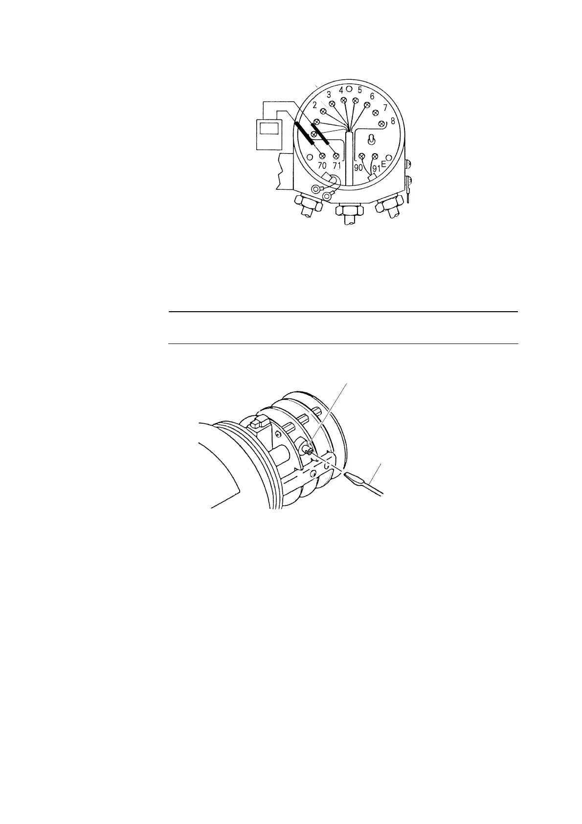
Ammeter
(or Voltmeter)
Connect an ammeter (or voltmeter).
③ Set the output signal to the desired value. ⋅⋅⋅⋅⋅⋅ Open the front cap. Then, set the output signal to
the desired value by turning the adjustable knob of VR4 with a screw driver referring to the
ammeter (or voltmeter) as shown in the figure below.
【IMPORTANT】 • When opening the front cap, make sure not to allow any water or rain
water to get into the Transmitter.
Adjustable Knob, VR4
Screw Driver
Set the output signal to the desired value.
〔NOTE〕 • Refer to “〔NOTE〕
⋅
Conversion Method to the Output Signal from the Indicated Value
on the digital display” described at the step ⑨ in “7.6 Adjustment of Output Signal of
the Transmitter”.
④ Close the rear cap. ⋅⋅⋅⋅⋅⋅ Disconnect the ammeter (or voltmeter) and connect the lead wires to
terminals “70(+), 71(-)” like before. Then, close the rear cap.
⑤ Change to “Measurement” mode. ⋅⋅⋅⋅⋅⋅ Turn the mode switch to “”Measurement mode (MEAS)
and the pilot lamp is lit continuously. Then, put the knob cover back in place and tighten 2 fixing
screws for the knob cover.