Model: CD-36D 7.6 Adjustment of Output Signal of the Transmitter
-
30
-
Ammeter
(or Voltmeter)
Connect an ammeter.
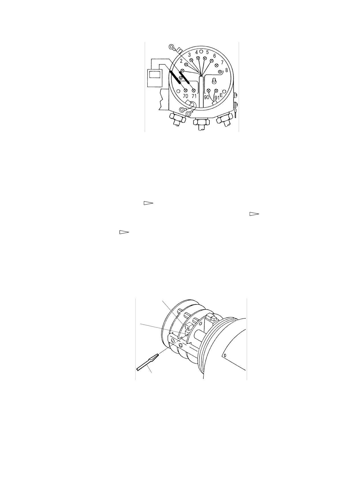
④ Adjust the zero point of the output signal. ⋅⋅⋅⋅⋅⋅ Open the front cap. Then, adjust the indication of
the ammeter (or Voltmeter) to the following value by turning the adjustable knob of VR3 with a
screw driver.
• In the case the output signal is 4 to 20mA DC 4mA
• In the case the output signal is 1 to 5V DC 1V
⑤ Connect the lead wire “1” ⋅⋅⋅⋅⋅⋅ (
④Connect the lead wire “1” in “5.(1) Zero Calibration”)
⑥ Analyze the residual chlorine in the sample with another method. ⋅⋅⋅⋅⋅⋅ (
“② Analyze
the residual chlorine in the sample with another method.” in “5.(2) Span Calibration”)
⑦ Adjust the span. ⋅⋅⋅⋅⋅⋅ (
“③ Adjust the span.” in “5.(2) Span Calibration”)
⑧ Adjust the span value of the output signal. ⋅⋅⋅⋅⋅⋅ Placing the Transmitter under the state for
measurement of sample water, adjust the indication of the ammeter (or Voltmeter) by turning the
adjustable knob of VR2 so that the ammeter (or Voltmeter) shows the output signal (mA or V)
converted from the indicated value on the digital display (mg/L).
Adjustable Knob, VR2
(For Span Adjustment of
Output Signal)
Adjustable Knob, VR3
(For Zero Adjustment of
Output Signal)
Screwdriver
Adjustment of Output Signal