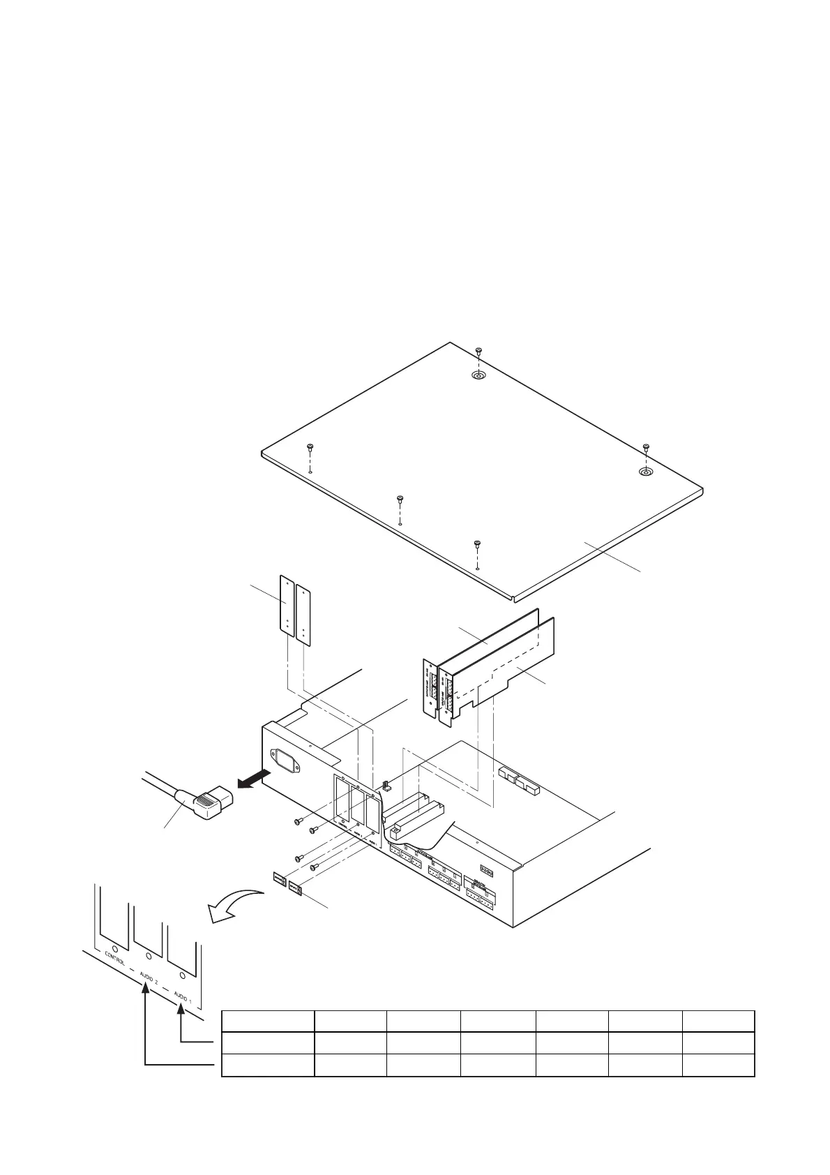
Step 1. Remove the power cord from the DP-0206.
Step 2. Remove 5 screws to detach the top panel.
Step 3. Detach the cover of the module slot to be used (AUDIO 1 or AUDIO 2) depending on the input/output
configuration by removing two screws.
Step 4. Install the optional module in the corresponding slot. (Refer to p. 9.) To achieve this, fully insert the
module into the unit's connector (CN1 or CN2), then fix the module front to the unit's rear panel using
screws.
Caution: Take care not to touch the parts or terminals on the circuit board of both the unit and module
to avoid failures due to static electricity.
Step 5. Affix the seal (attached to the DQ-A01 and DQ-A02) showing the input and output numbers of the
mounted module to the unit.
Step 6. Replace the top panel.
Note: The illustration is an example of the unit
with 4-IN/8-OUT configuration.
2-IN/6-OUT 2-IN/8-OUT 2-IN/10-OUT 4-IN/6-OUT 4-IN/8-OUT 6-IN/6-OUT
––
OUTPUTS 7, 8 INPUTS 3, 4 INPUTS 3, 4 INPUTS 3, 4
–
OUTPUTS 7, 8
OUTPUTS 9, 10
–
OUTPUTS 7, 8 INPUTS 5, 6
AUDIO 1
AUDIO 2
I/O configuration
[Input/output configuration and I/O number seal]
 Loading...

