29
[Binary mode]
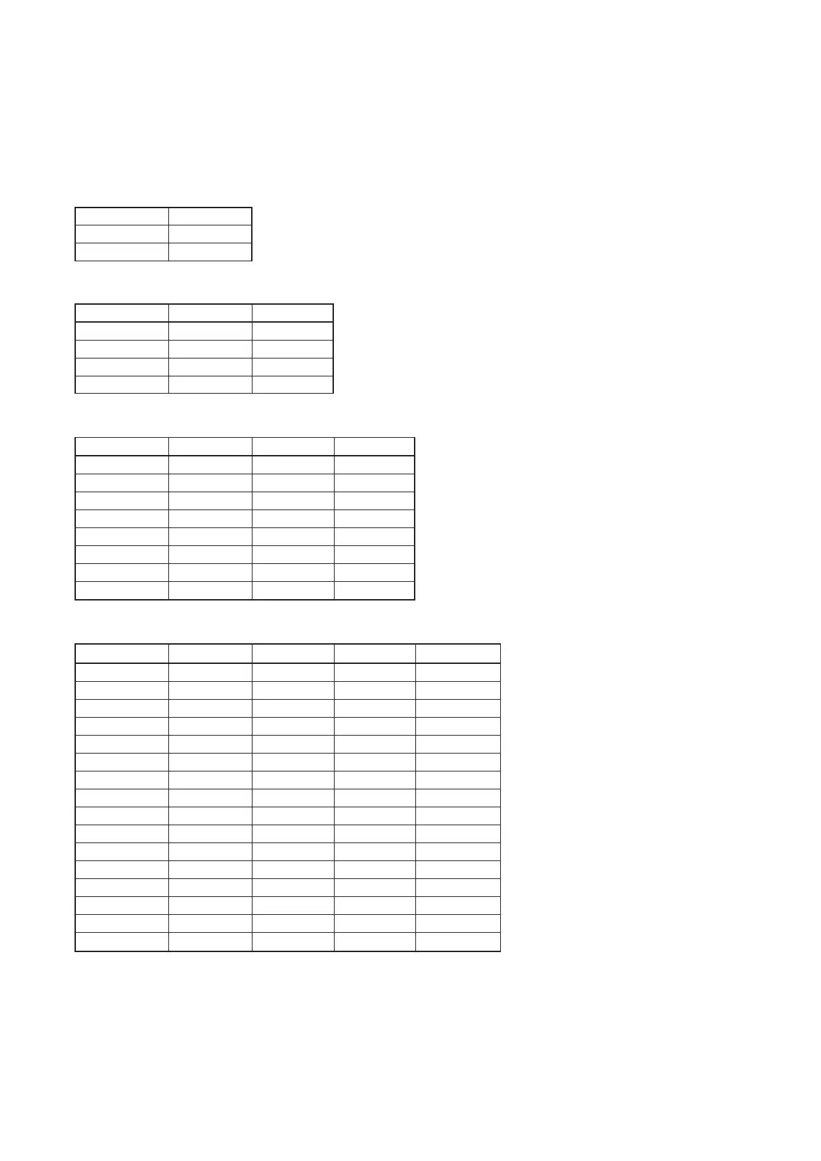
The following tables show the relationship between the state to be assigned to the terminal and the pattern
memory to be recalled:
(In the tables, [
O
] stands for a short circuit, and [–] stands for an open circuit. )
Memory No. Terminal 5 Terminal 6 Terminal 7 Terminal 8
1
OOOO
2
OOO
–
3
OO
–
O
4
OO
––
5
O
–
OO
6
O
–
O
–
7
O
––
O
8
O
–––
9 –
OOO
10 –
OO
–
11 –
O
–
O
12 –
O
––
13 ––
OO
14 ––
O
–
15 –––
O
16 ––––
• Selecting 16 memories using Terminals 5, 6, 7 and 8
The pattern memory is switched if the corresponding state is assigned to the desired pattern memory and is
maintained for more than 500 ms. Maintain the terminal state until the pattern memory is next switched.
Memory No. Terminal 6 Terminal 7 Terminal 8
1
OOO
2
OO
–
3
O
–
O
4
O
––
5 –
OO
6 –
O
–
7 ––
O
8 –––
• Selecting 8 memories using Terminals 6, 7 and 8
Memory No. Terminal 7 Terminal 8
1
OO
2
O
–
3 –
O
4 ––
• Selecting 4 memories using Terminals 7 and 8
Memory No. Terminal 8
1
O
2 –
• Selecting 2 Memories using Terminal 8
 Loading...

