TH2523 Series Operation Manual Ver1.2
6
RS-232C
DEVICETRIGGER
GPIB
HANDLER
!
TO AVOID ELECTRIC SHOCK,
THE POWER CORD PROTECTIVE GROUNDING
CONDUCTOR MUST BE CONNECTED TO GROUND.
DISCONNECT POWER SUPPLY BEFORE
REPLACING FUSE.
WARNING
FUSE
220V/50Hz 80VA
T1AL 250V
~
RATING
贴标签
1 2
5 4 3678
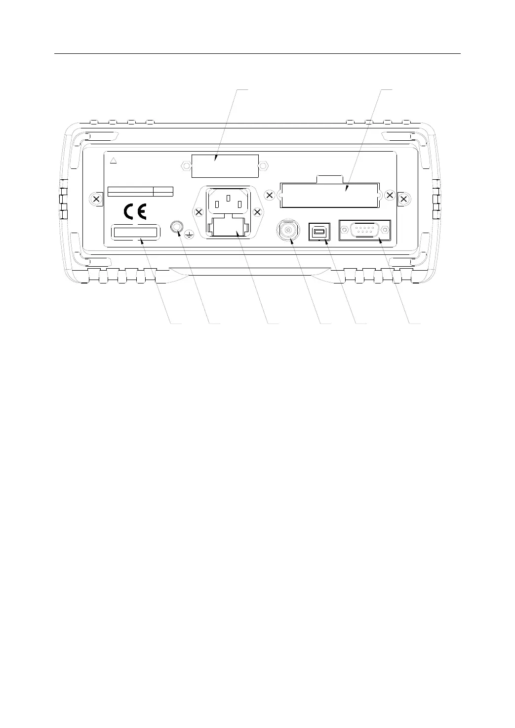
Figure 2-2 Rear Panel
(1) GPIB Interface (Option)
The GPIB interface is used to communicate with PC and further construct a GPIB test system.
(2) HANDLER Interface
Through HANDLER interface, an automatic test system can be conveniently constructed to
realize auto test. TH2523 will output bin comparator result signals and handshake signals by
this interface, meanwhile, “start up” signal will also be sent to the instrument by it.
(3) RS232C Serial Interface
It realizes the serial communication of the instrument with PC.
(4) USB Interface
PC can remotely control TH2523 through USB DEVICE.
(5) TRIGGER
It is used to externally trigger signals. In this mode, user can apply footswitch (option) to make
triggering measurement.
(6) Power Socket
It is used to input AC power.
(7) Ground Terminal
This terminal connects the instrument chassis thus to protect or shield ground connection.
(8) Nameplate
It shows the instrument model.