Feedback Controlyzer DigiLock 110
Page 28
Status: 5.12.17
8.2.1.8 PDH
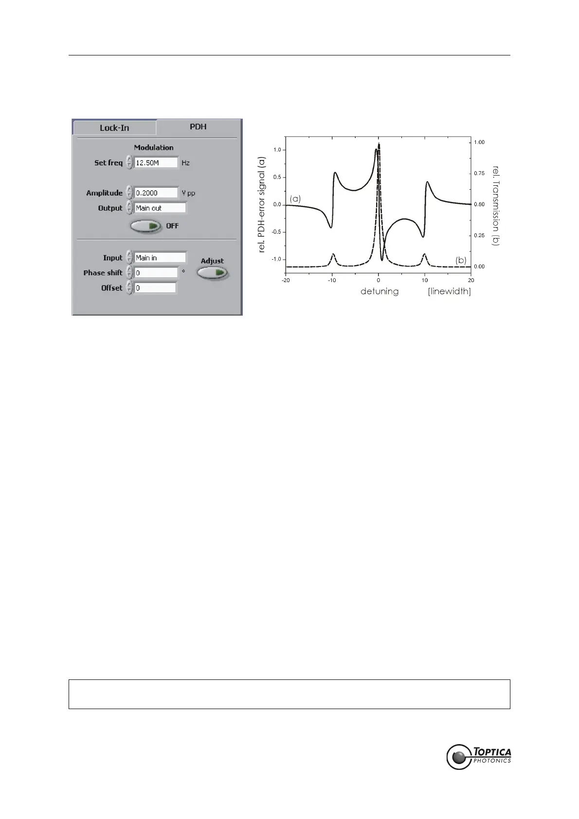
Figure 16 Left: PDH module
Right: Schematic error signal of a single resonance generated with the Pound-Drever-Hall
modulation technique. The sidebands - exaggerated for Illustration - can be seen at about
10 MHz.
The principle of operation is similar to the Lock-In module but the modulation frequencies are typically
higher than the characteristic linewidth of the resonance. The available modulation frequencies are
given by fractions of 25 MHz (25 MHz, 12.5 MHz, 6.25 MHz, 3.13 MHz, 1.56 MHz).
Modulation: A frequency modulation is applied to one of the outputs to generate an
error signal by mixing the detected signal with a local oscillator. The
modulation is automatically switched on for locking. It can be switched
manually with the ON/OFF button. Manual activation is only needed to
adjust the phase shift or in manual lock mode.
Set freq: Modulation frequency in Hz.
Amplitude: Peak-to-peak amplitude of the modulation signal in Volts.
Output: Output channel to which the modulation signal is applied.
Modulation ON/OFF: Modulation switched ON/OFF.
Input: Input source for the module (Main in, Aux in).
Phase shift: Phase shift in degrees between the output and the local oscillator sig-
nal.
Offset: Offset in units corresponding to the oscilloscope display. The offset is
subtracted from the demodulated signal.
Adjust: Adjusts the phase of the demodulated error signal to match the deriva-
tive of the spectrum signal. The progress is indicated on the progress bar
in the status display. In order for the algorithm to work properly be sure
that the resonance of interest is visible in the AutoLock display during
operation.
NOTE ! Due to signal processing limitations it is recommended to optimize the lock with the
demodulated <PDH out> signal, and not the modulated input signal. (see section 9.6).
 Loading...