8. DigiLock User Interface (DUI)
Page 27
Status: 5.12.17
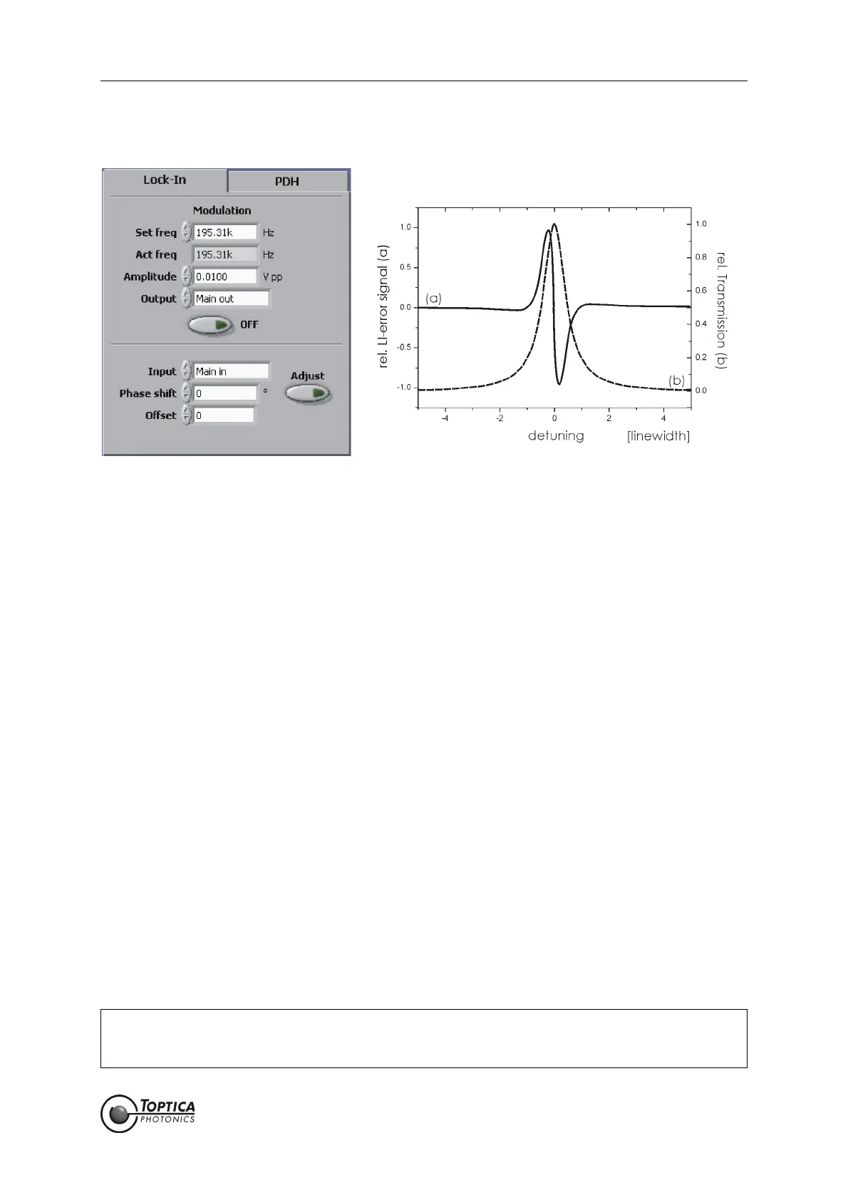
8.2.1.7 Lock-In
Figure 15 Left: Lock-in module
Right: Schematic error signal of a single resonance generated with the Lock-In modulation
technique
The Lock-In module can be used to generate an error signal for the PID controller with the Lock-in modu-
lation/demodulation scheme. Since it generates the derivative of the original signal, it allows the user to
stabilize a system to a peak or a valley.
Modulation: A frequency modulation is applied to one of the outputs to generate an
error signal by mixing the detected signal with the internal local oscilla-
tor. The modulation is automatically switched on for locking. It can be
switched manually with the ON/OFF button. Manual activation is only
needed to adjust the phase shift or in manual lock mode.
Set freq: The desired modulation frequency in Hz.
Act freq: The actual modulation frequency in Hz.
Due to signal processing limitations only discrete modulation frequen-
cies are possible (even fractions of 781.25 kHz). The closest frequency is
chosen automatically.
Amplitude: Peak-to-peak amplitude of the modulation signal in Volts.
Output: Output channel for the modulation signal.
Modulation ON/OFF: Modulation switched ON/OFF.
Input: Input source for the module (Main in, Aux in).
Phase shift: Phase shift in degrees between the output and the local oscillator.
Offset: Offset in units corresponding to the oscilloscope display. The offset is
subtracted from the demodulated signal.
Adjust: Adjusts the phase of the demodulated error signal to match the deriva-
tive of the spectrum signal. The progress is indicated on the progress bar
in the status display. In order for the algorithm to work properly be sure
that the resonance of interest is visible in the AutoLock display during
operation.
NOTE ! Due to signal processing limitations it is recommended to optimize the lock, e.g. minimal
rms error or spectrum analysis, using the demodulated <LI out> signal, and not the input
signal which is modulated. (see section 9.6).
 Loading...