Rev. B
Workman 1100/1110/2100/2110 Page 6 – 7 Electrical System
Component Testing
For accurate resistance and/or continuity checks, elec-
trically disconnect the component being tested from the
circuit (e.g. unplug the ignition switch connector before
doing a continuity check on the switch).
NOTE: See the Briggs and Stratton Repair Manual
for 4 Cycle, V–Twin Cylinder, OHV Head Engines or
the Kohler Service Manual for Command Pro CS Se-
ries Engines for additional component testing informa-
tion.
CAUTION
When testing electrical components for continu-
ity with a multimeter (ohms setting), make sure
that power to the circuit has been disconnected.
Ignition Switch
Two types of ignition (key) switches have been used on
the Workman 1100,1110, 2100, and 2110.
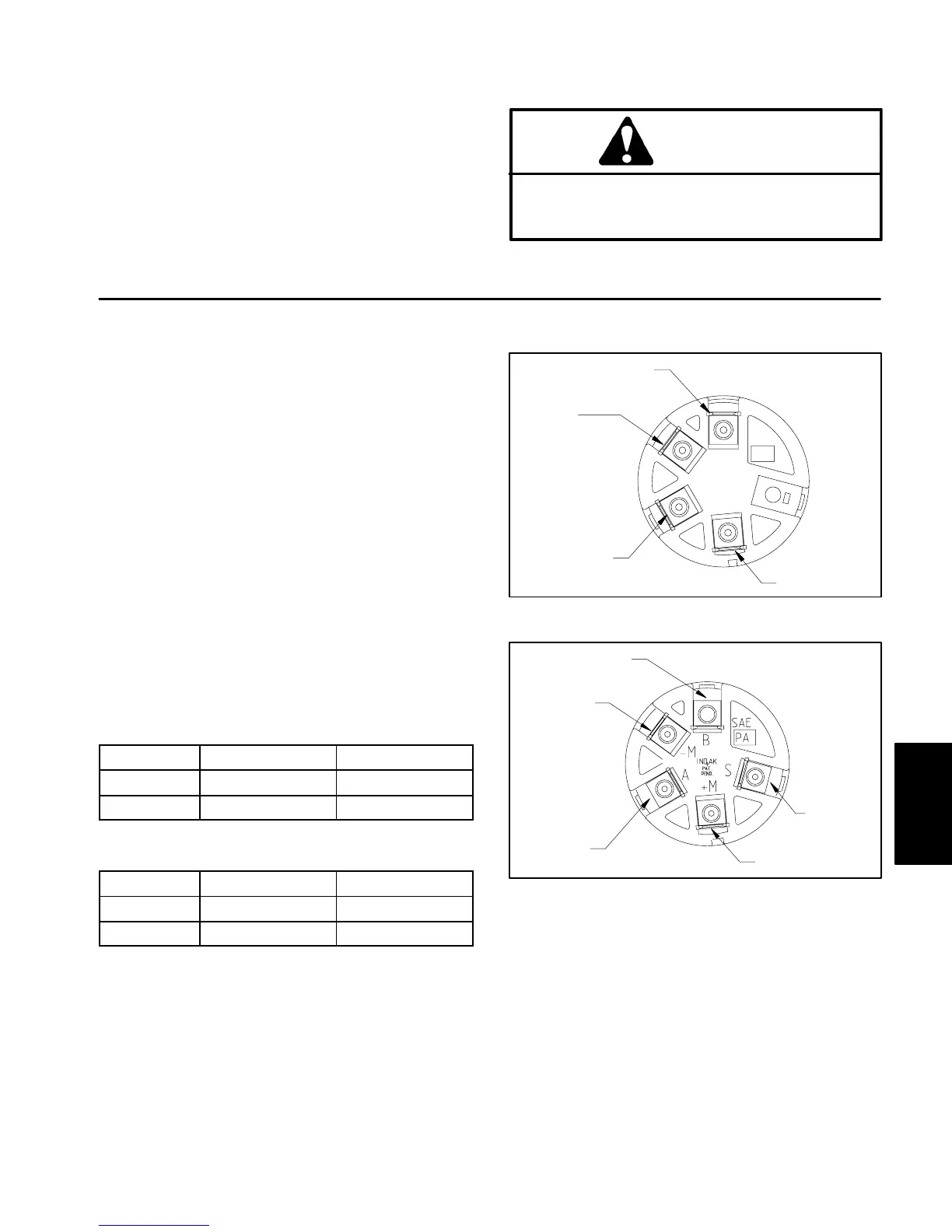
Early production switches had four switch terminals and
two key positions (OFF and RUN). The switch terminals
are marked as shown in Figure 3.
Later production switches had five switch terminals and
three key switch positions, but only two or those posi-
tions are used (OFF and RUN). The switch terminals are
marked as shown in Figure 4.
Testing
The circuitry of the ignition switch is shown in the charts
below. With the use of a multimeter (ohms setting), the
switch functions may be tested to determine whether
continuity exists between the various terminals for each
key position. Verify continuity between switch terminals.
1. For 2 position switch (Fig. 3):
POSITION
CIRCUIT “MAKE” AMPS
OFF +M + –M 1
RUN 1 + 2 15
2. For 3 position switch (Fig. 4):
POSITION
CIRCUIT “MAKE” AMPS
OFF +M + –M 1
RUN A + B 15
TERMINAL 1
TERMINAL 2
TERMINAL +M
TERMINAL –M
SAE
PA
1
+M
–M
2
SAE
Figure 3
END VIEW
2 POSITION SWITCH
Figure 4
END VIEW
TERMINAL B
TERMINAL –M
TERMINAL A
TERMINAL S
TERMINAL +M
3 POSITION SWITCH
Electrical
System
 Loading...