Rev. A Workman 1100/1110/2100/2110
Drive Train
Page 5 – 4
Adjustments
Adjust Ground Speed (Vehicles With Transaxle Governor)
Note: All Workman 1100 and 1110 models are
equipped with a transaxle governor. Workman 2100 and
2110 models with serial numbers below 240000000 are
also equipped with a transaxle governor.
Vehicles operating at ground speeds greater than
the recommended speed will require further
distances to fully stop. Do not adjust ground
speed greater than specified.
WARNING
1. Park machine on a level surface, stop engine, and re-
move key from the ignition switch. Raise and latch cargo
bed.
WARNING
Before jacking up the machine, review and follow
Jacking Instructions in Chapter 1 – Safety.
2. Jack up rear of vehicle so both rear wheels are at
least 1 inch (25mm) off the ground with the rear axle
tubes supported on jack stands.
3. Chock front and rear of both front tires to prevent the
vehicle from moving.
4. Lock transaxle into neutral (see Transaxle Neutral
Position in Chapter 1 – Safety).
5. Verify ground speed as follows:
A. Start engine and hold accelerator pedal to the
floor.
B. Verify driven clutch RPM with a tachometer. With
the accelerator pedal to the floor, the driven clutch
speed should be as follows:
MODEL
DRIVEN CLUTCH RPM
1100 2900 – 3000 RPM
2100 3250 – 3350 RPM
2110 2950 – 3050 RPM
C. If unable to identify the driven clutch RPM, an al-
ternate method to verify ground speed would be to
determine the distance that the vehicle will travel in
three (3) seconds with the accelerator pedal to the
floor. Use the following chart to determine if vehicle
ground speed is correct:
MODEL
DISTANCE IN
3 SECONDS
GROUND
SPEED
1100 62 ft (18.9 m) 14 mph (23 kph)
2100/2110 70 ft (21.3 m) 16 mph (26 kph)
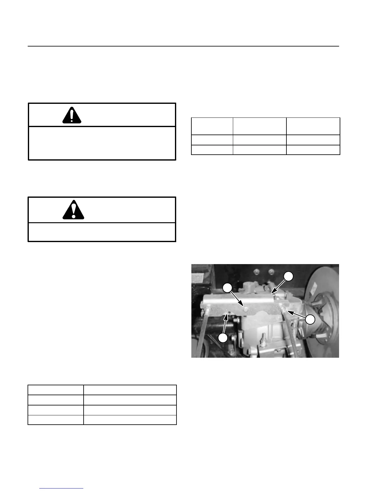
6. If ground speed adjustment is necessary, drill out an-
odized rivet and retain anti–tamper bracket for rein-
stallation (Fig. 4).
7. Adjust throttle cable (accelerator pedal to transaxle)
at the cable bracket until the correct driven clutch RPM
is obtained with the accelerator pedal fully to the floor
(Fig. 4).
8. Reinstall anti–tamper bracket to the cable bracket
with a new anodized rivet (Toro P/N 99–7122) (Fig. 4).
9. Lower machine to ground. Lower cargo bed.
1. Anodized rivet
2. Anti–tamper bracket
3. Throttle cable
4. Cable bracket
Figure 4
3
1
2
4
 Loading...