Workman 1100/1110/2100/2110Page 7 – 10Chassis, Wheels, and Brakes (Rev. B)
Adjust Front Ride Height
1. If front ride height adjustment is needed, park ma-
chine on a level surface, stop engine, set parking brake,
and remove key from the ignition switch.
WARNING
Before jacking up the machine, review and follow
Jacking Instructions in Chapter 1 – Safety.
2. Jack front end of the vehicle off the ground.
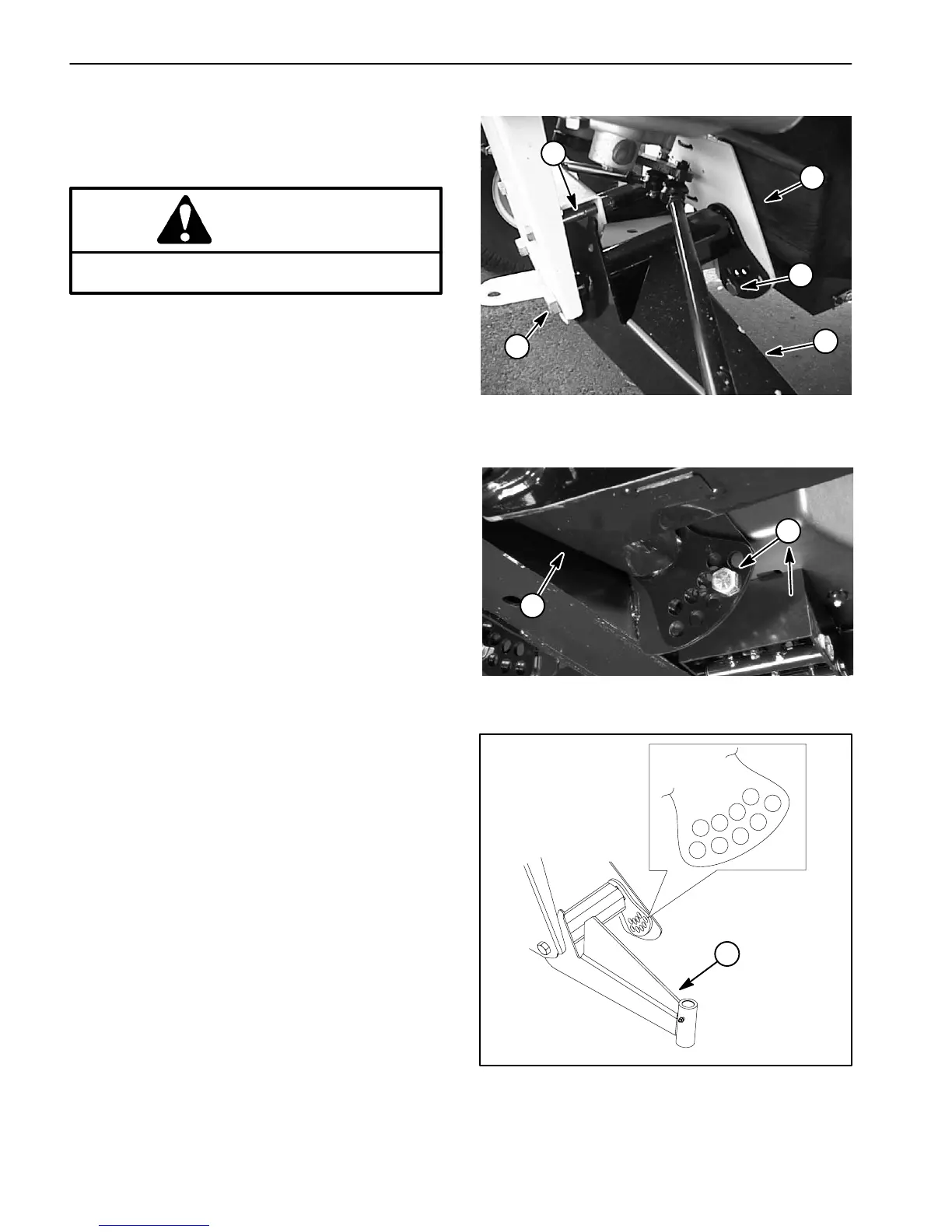
3. Remove travel limiting bolt (Fig. 5).
4. Loosen centering bolts (front and rear) in the A–arm
(Fig. 5).
5. Remove ride height adjustment bolt (Fig. 6).
NOTE: The A-arms suspension inserts are made with
rubber and have different spring rates. Because of the
different spring rates, the A-arms come adjusted from
the factory based on that spring rate. Generally, the ride
height adjustment bolts will be installed in hole number
2, 3, or 4 (Fig. 7) and it may be different from the left side
(driver side) to the right side (passenger side). If the A-
arms look like they are sagging, then they should be ad-
justed to the next higher number (Fig. 7). Each hole
equals about 3/4 inch (19 mm) of adjustment at the
wheel. Ride height should be adjusted to the next higher
position when adding heavy attachments or carrying
heavy loads often.
6. Rotate A–arm to the desired position and replace
ride height adjustment bolt.
7. Tighten and torque ride height adjustment bolt from
135 to 165 ft-lb (183 to 224 N–m).
NOTE: To reinstall the travel limiting bolt, it may be nec-
essary to lower the machine to the ground.
8. Replace travel limiting bolt (Fig. 5 and 6).
9. Tighten and torque centering bolts from 240 to 290
ft-lb (325 to 393 N–m).
10.Repeat procedure on opposite side of the vehicle.
11. Recheck front ride height.
12.After front ride height is adjusted, check and adjust
front wheel toe–in (see Adjust Front Wheel Toe–in).
1. Travel limiting bolt
2. Centering bolt
3. A–arm
4. Ride height adj. bolt
Figure 5
240 to 290 ft–lb
(325 to 393 N–m)
3
2
1
2
4
1. Ride height adj. bolt 2. A–arm
Figure 6
135 to 165 ft–lb
(183 to 224 N–m)
2
1
1. Front A–arm (LH shown)
Figure 7
1
2
3
4
5
6
7
8
0
1
 Loading...