Workman 1100/1110/2100/2110 Page 6 – 9 Electrical System
Starter Solenoid
NOTE: Prior to taking small resistance readings with a
digital multimeter, short the meter test leads together.
The meter will display a small resistance value (usually
0.5 ohms or less). This resistance is due to the internal
resistance of the meter and test leads. Subtract this val-
ue from the measured value of the component you are
testing.
1. Make sure engine is off. Disconnect battery. Discon-
nect solenoid electrical connections.
2. Apply 12 VDC directly across the solenoid coil posts.
The solenoid should click. Make sure resistance across
the main contact posts is less than 1 ohm.
3. Remove voltage from solenoid coil posts. The sole-
noid should click. Make sure resistance across the main
contact posts is infinite ohms.
4. Resistance across the solenoid coil posts should be
approximately 15.5 ohms.
5. Replace starter solenoid if necessary.
6. Reconnect electrical connections to solenoid: posi-
tive battery cable and wire to fuse block on one main
contact post and starter/generator cable and wire to reg-
ulator on the other main contact post. Reconnect bat-
tery.
NOTE: Voltage is supplied to the solenoid on the Work-
man whenever the key is in the RUN position and the ac-
celerator pedal is depressed.
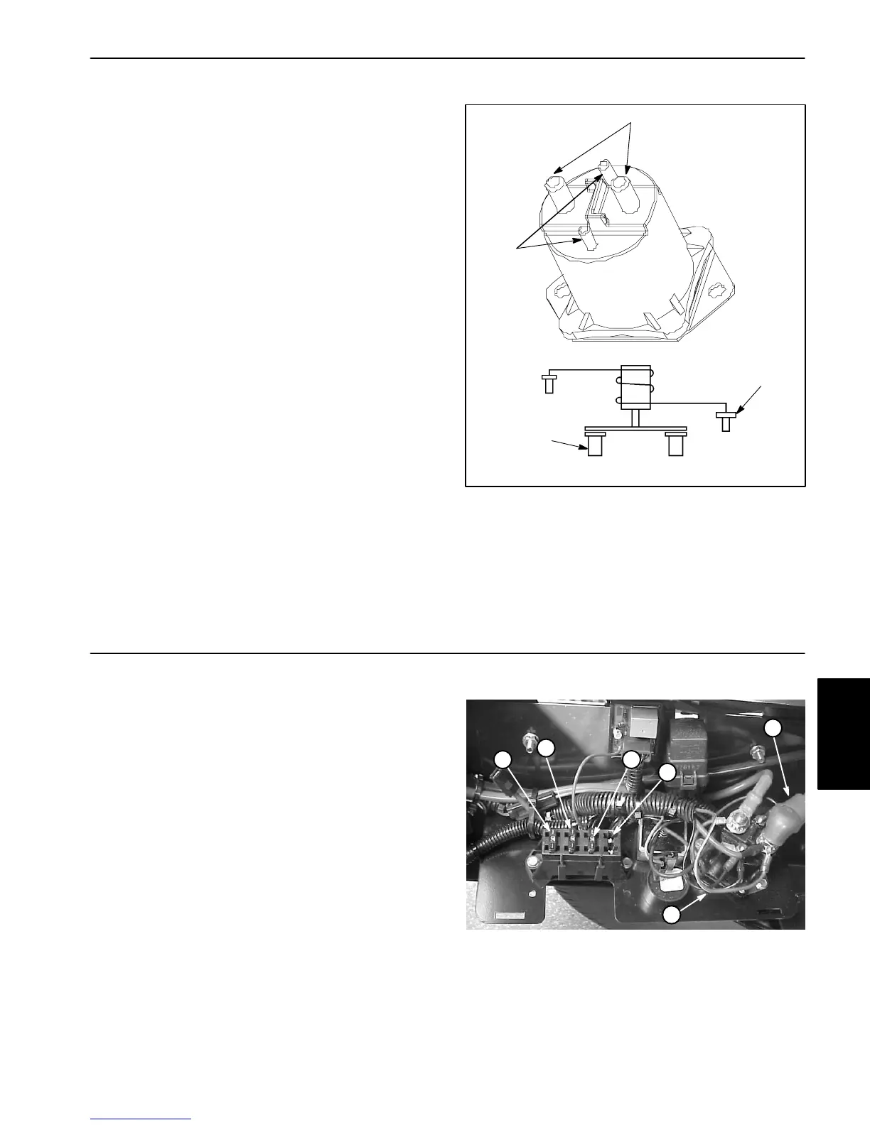
Figure 8
WIRING
DIAGRAM
1. Main posts (copper)
2. Solenoid posts (steel)
1
2
2
1
Fuse Block
There are 3 fuses in the vehicle’s electrical system. They
are located beneath the bed in a box on the right hand
side of the frame.
Fuses can be removed to check conti-
nuity. The test meter should read less than 1 ohm.
Fuses supply power to the following (Fig. 9):
1. The extreme left 10 ampere fuse supplies power to
the start/run systems.
2. The middle left 10 ampere fuse supplies power to the
lights.
3. The middle right 10 ampere fuse supplies power to
the power point. A maximum of a 15 ampere fuse is al-
lowed.
4. The extreme right fuse supplies power to an optional
bed lift (if equipped).
Figure 9
1. Ignition system fuse
2. Lights fuse
3. Power point fuse
4. Option
5. Positive battery cable
6. Wire to fuse block
1
2
3
4
5
6
Electrical
System

 Loading...