Workman 1100/1110/2100/2110Page 7 – 18Chassis, Wheels, and Brakes (Rev. B)
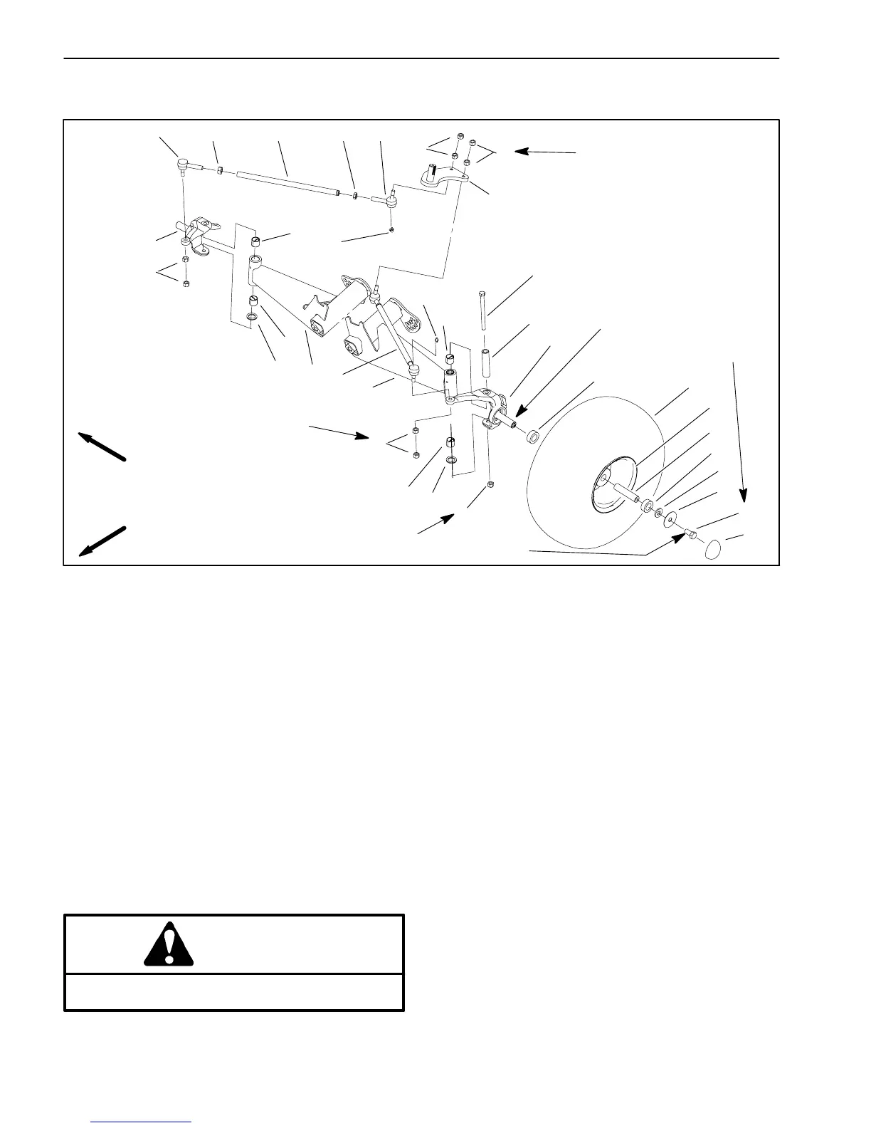
Lower Steering and Front Wheels (Workman 1100 and 2100)
1. Tire
2. Front wheel
3. Plastic dust cap
4. Cap screw
5. Large flat washer
6. Flat washer
7. Bearing
8. Spacer
9. Spindle (LH)
10. Lock nut
11. Thrust washer
12. Cap screw (king pin)
13. Jam nuts
14. Tie rod assembly
15. Ball joint (RH thread)
16. Jam nut (RH thread)
17. Tie rod
18. Jam nut (LH thread)
19. Ball joint (LH thread)
20. Pitman arm
21. A–arm (LH)
22. A–arm (RH)
23. Kingpin sleeve
24. Bushing
25. Spindle (RH)
26. Grease fitting
Figure 12
FRONT
RIGHT
10
25
15
26
26
12
9
16
17
18
19
13
1
6
5
4
3
2
8
7
14
13
24
24
22
21
11
20
13
13
7
23
Antiseize
135 to 165 ft–lb
(183 to 224 N–m)
20 to 25 ft–lb
(27 to 34 N–m)
75 to 100 ft–lb
(102 to 136 N–m)
24
24
11
20 to 25 ft–lb
(27 to 34 N–m)
lubricant
Thread locking
compound
NOTE: Both front wheels (2) have two bearings (7) and
one spacer (8).
NOTE: Both tie rod assemblies (14) consist of the fol-
lowing parts: ball joints (15 and 19), jam nuts (16 and
18), and tie rod (17).
Removal
1. Park machine on a level surface, stop engine, set
parking brake, and remove key from the ignition.
WARNING
Before jacking up the machine, review and follow
Jacking Instructions in Chapter 1 – Safety.
2. Chock wheels not being jacked up. Jack front wheel
off the ground, and place blocks beneath the frame.
3. Remove tire and front wheel as follows:
A. Remove plastic dust cap carefully from the wheel
to prevent damage to the cap.
B. Remove cap screw and washers securing the
wheel to the spindle. Slide tire and wheel assembly
from the spindle shaft.
4. Remove spindle as follows:
A. Remove jam nuts securing tie rod ball joint to the
spindle. Separate ball joint from the spindle. Remove
tie rod from Pitman arm if necessary.
B. Remove lock nut and cap screw (king pin) secur-
ing the spindle to the A–arm. Separate spindle from
the A–arm.
 Loading...