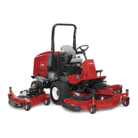
Figure81
1.Casterwheel
3.Bearing
2.Caster-pivotarm
4.Bearingspacer
2.Removethebearingfromthewheelhubandallowthe
bearingspacertofallout(Figure80andFigure81).
3.Removethebearingfromtheoppositesideofthe
wheelhub.
4.Checkthebearings,spacer,andinsideofthewheelhub
forwearandreplaceanydamagedparts.
5.Toassemblethecasterwheel,pushthebearinginto
thewheelhub.
Note:Wheninstallingthebearings,pressontheouter
faceofthebearing.
6.Slidethebearingspacerintothewheelhubandpush
theotherbearingintotheopenendofthewheelhub
tocaptivatethebearingspacerinsidethewheelhub.
7.Installthecaster-wheelassemblybetweenthecaster
forkandsecureitinplacewiththeboltandlocknut.
BladeMaintenance
BladeSafety
DANGER
Awornordamagedbladecanbreak,andapiece
ofthebladecouldbethrownatyouorbystanders,
resultinginseriouspersonalinjuryordeath.
Tryingtorepairadamagedblademayresultin
discontinuedsafetycerticationoftheproduct.
•Inspectthebladeperiodicallyforwearor
damage.
•Nevertrytostraightenabladethatisbentor
weldabrokenorcrackedblade.
•Replaceawornordamagedblade.
•Usecarewhencheckingtheblades.Wrapthebladesor
weargloves,andusecautionwhenservicingtheblades.
Onlyreplacetheblades;neverstraightenorweldthem.
•Onmulti-bladedmachines,takecareasrotating1blade
cancauseotherbladestorotate.
CheckingforaBentBlade
Afterstrikingaforeignobject,inspectthemachinefor
damageandmakerepairsbeforestartingandoperatingthe
equipment.Torqueallofthespindle-pulleynutsto176to
203N∙m(130to150ft-lb).
1.Positionthemachineonalevelsurface,raisethemower
deck,engagetheparkingbrake,putthetractionpedal
inNEUTRAL,putthePTOleverintheOFFposition,
shutofftheengine,andremovetheignitionkey.
Note:Blockthemowerdecktopreventitfrom
accidentallyfalling.
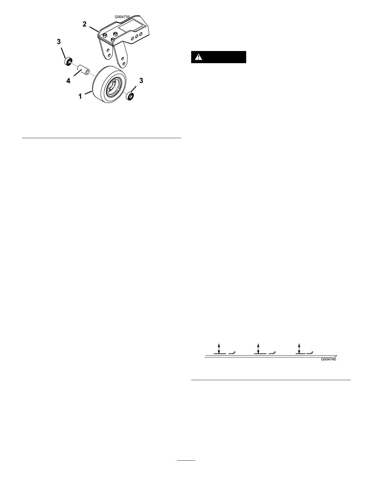
2.Rotatethebladeuntiltheendsfaceforwardand
backwardandmeasurefromtheinsideofthemower
decktothecuttingedgeatthefrontoftheblade
(Figure82).
Note:Rememberthisdimension.
Figure82
3.Rotatetheoppositeendofthebladeforwardand
measurebetweenthemowerdeckandcuttingedgeof
thebladeatthesamepositionasinstep2.
Note:Thedifferencebetweenthedimensions
obtainedinsteps2and3mustnotexceed3mm(1/8
inch).Ifthedimensionexceeds3mm(1/8inch),the
bladeisbentandmustbereplaced;refertoRemoving
andInstallingtheMowerBlade(s)(page58).
57