2.MeasuretherightbladeattheAlocation,fromalevel
surfacetothecuttingedgeofthebladetip(Figure99).
3.Recordthismeasurement.
4.MeasuretherightbladeattheBlocation,fromalevel
surfacetothecuttingedgeofthebladetip(Figure99).
5.Recordthismeasurement.
6.Themowerbladeshouldbe6to10mm(1/4to3/8
inch)loweratpositionAthanatpositionB(Figure99).
Ifitisnotcorrect,proceedtothefollowingsteps.
Note:Bothofthefrontswivelsneedtobeadjusted
thesameamounttomaintainequalchaintension.
7.Loosenthefrontswiveljamnuts,atthefrontofthe
rightandleftswivels,approximately13mm(1/2inch)
(Figure98).
8.Adjusttheliftnutsonboththeleftandtherightsideof
themachinetoachieve6to10mm(1/4to3/8inch)
lowerinfrontatAthanintherearatB(Figure98).
9.Tightenbothswiveljamnutsagainstthefrontswivel
tolocktheheight.
10.Checktomakesurethatthereisequaltensiononthe
chainsandadjustagainifneeded.
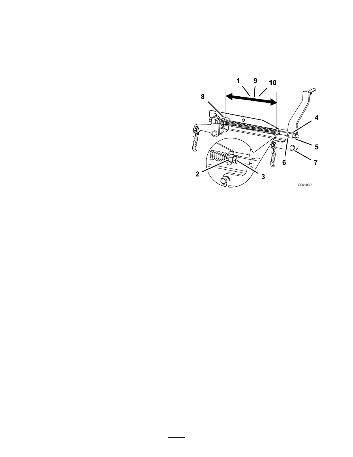
AdjustingtheCompressionSpring
1.Raisethemowerliftlevertothetransportposition.
2.Checkthedistancebetweenthe2largewashers,it
needstobe28.2cm(11-1/8inches)for52inchmower
decks,26.7cm(10-1/2inches)for60inchmower
decks,or29.2cm(11-1/2inches)for72inchmower
decks(Figure100).
g002479
Figure100
1.28.2cm(11-1/8inches)
betweenthelargewashers
for52inchmowerdecks
6.Liftnut
2.Frontnut7.Front-supportarm
3.Spring-jamnut
8.Largewasher
4.Frontswivel
9.26.7cm(10-1/2inches)
betweenthelargewashers
for60inchmowerdecks
5.Swiveljamnut10.29.2cm(11-1/2inches)
betweenthelargewashers
for72inchmowerdecks
3.Adjustthisdistance,bylooseningthespring-jamnut
andturningthenutinfrontofeachspring(Figure100).
Note:Turningthenutclockwiseshortensthespring;
counter-clockwiselengthensthespring.
4.Lockthenutintopositionbytighteningthespring-jam
nut(Figure100).
67