8
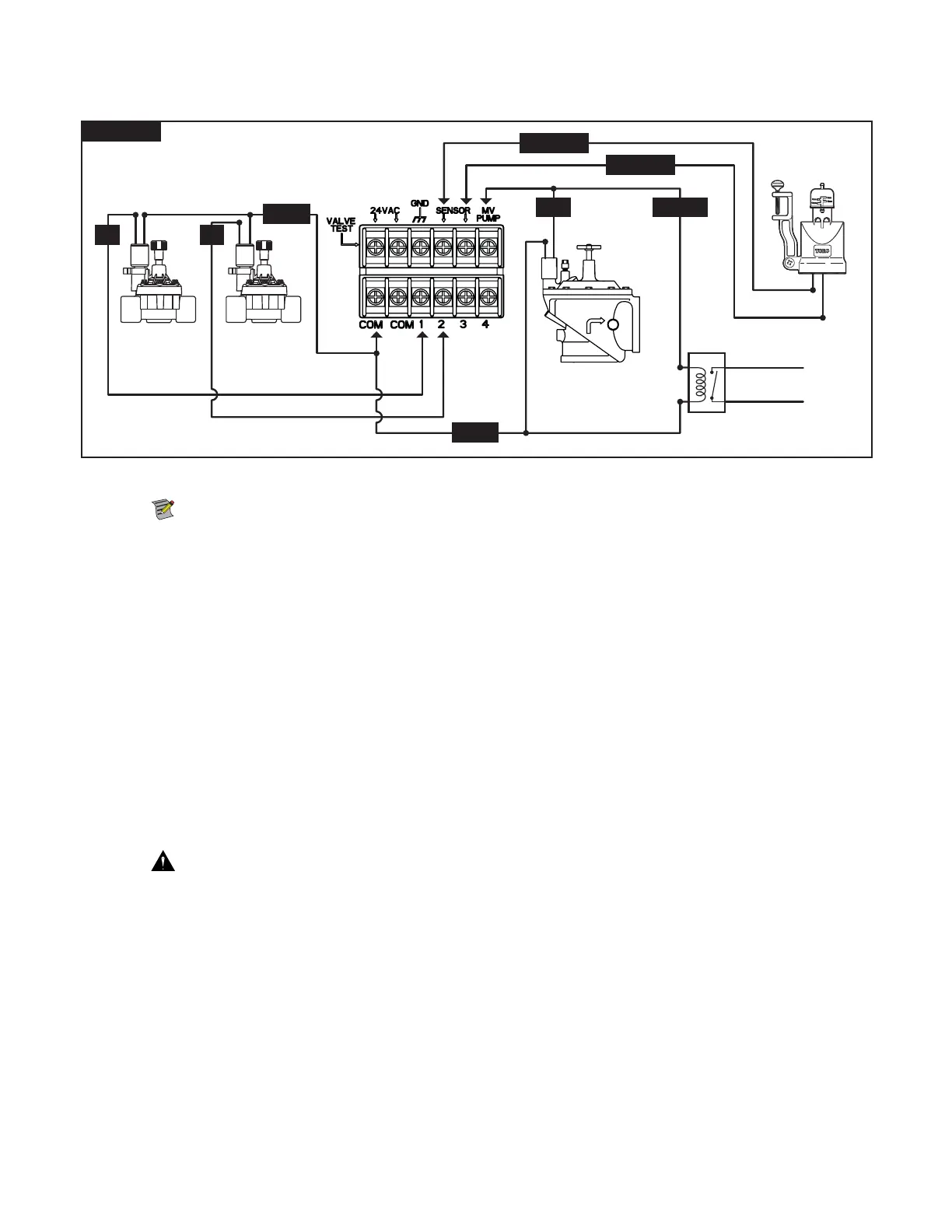
Valve, Pump Relay and Sensor Installation
Figure 13
1 2
MV PUMP
SENSOR
SENSOR
COM
COM
Step 1 – Route valve wires from the valves, master valves, pump relay and/or sensor into the controller cabinet.
Note: 18 AWG (1.0 mm
2
) multi-wire sprinkler valve connection cable can be used. is cable is insulated for direct burial
and is color-coded to simplify installation. It can be routed directly into the controller through the access hole provided for
valve wire conduit (if conduit is not used).
Step 2 – $POOFDUWBMWFTNBTUFSWBMWFTBOEQVNQTUBSUSFMBZUPUIFWBMWFXJSFT - Connect the white color-coded wire from the cable
to one wire from each valve solenoid and/or pump relay. (Either of the two wires from the solenoid or pump relay can be used
for this connection.) is connection will be designated as the valve common wire.
Connect a separate cable wire to the remaining wire from each valve solenoid. Note the wire color-code used for each valve and
the zone it controls. You will need this information when connecting the valve wires to the controller.
$POOFDUTFOTPSUPUIFWBMWFXJSFT - Connect any two unused color-coded wires to the sensor. Note the color-code of the
sensor wires for installation.
Step 3 – Secure all wire splices using wire nut connectors. To prevent corrosion and possible short circuits, always use an insulated wire
nut, grease cap or similar waterproong method.
Step 4 – $POOFDUWBMWFTXJSFTUPUIFDPOUSPMMFS- Secure the valve common wire (white) to either of the two terminals labeled COM.
Secure the individual valve wires to the appropriate zones they control, Zone 1 valve to terminal 1, Zone 2 valve to terminal 2, etc.
$POOFDUNBTUFSWBMWFQVNQSFMBZXJSFTUPUIFDPOUSPMMFS- Secure the valve common wire (white) to either of the two
terminals labeled COM. Secure the Master Valve or Pump Relay wire to the terminal labeled .716.1.
$BVUJPO To prevent controller damage, do not connect the pump motor starter directly to the controller.
$POOFDUTFOTPSXJSFTUPUIFDPOUSPMMFS- Remove the jumper wire from the SENSORS terminals. Secure the two sensor wires
to the sensor terminals. Refer to the provided sensor instructions for further installation instructions.
Step 5 – Test for proper operation.