5
Installation
A
B
C
D
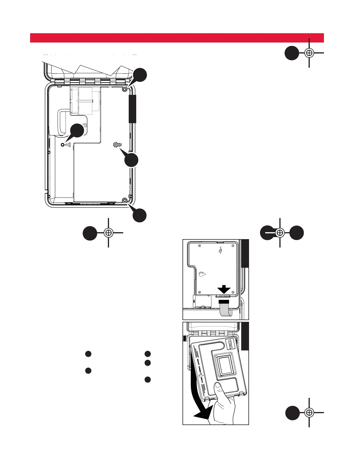
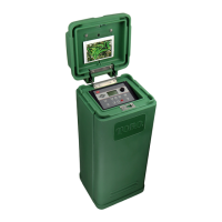
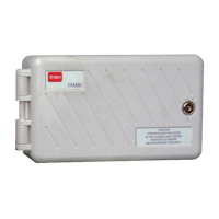
Cabinet Installation
Use this page as a template to mark the screw location of the EVOLUTION
TM
cabinet.
ere are two mounting options for the EVOLUTION
TM
. e rst option allows you
to mount the cabinet with three screws and the second option allows you to mount the
cabinet with two screws. For safe and reliable operation, select an installation site that
can provide the following conditions:
t'PS*OEPPSNPEFMDPOUSPMMFST - Inside a garage or other structure which will provide
protection from the weather.
t'PS0VUEPPSNPEFMDPOUSPMMFST - Protection from irrigation spray, wind and snow. A
shaded location is recommended.
tAccess to a grounded AC power source (within 4' [1.2 m] for indoor models) which
is not controlled by a switch or utilized by a high current load appliance, such as a
refrigerator or air conditioner.
tAccess to the sprinkler control valve wiring and optional accessory wiring.
A
B
D
C
Option 1
Step 1 – Unplug the controller panel ribbon cable. Open the front panel about
90
º
and detach it from the cabinet by pulling the bottom portion
upwards. Removing it from the cabinet allows you to access the
mounting location.
Step 2 – Mark the mounting screw location
A
,
B
and
D
.
Step 3 – Drill 1/8" (3mm) pilot holes at the marked locations.
Step 4 – Secure the cabinet with screws.
Option 2
Step 2 – Mark the mounting screw location
C
and
D
.
Step 3 – Drill 1/8" (3mm) pilot holes at the marked locations.
Step 4 – Secure the cabinet with screws.
Figure 3
Figure 4 Figure 5