ProPass 200Page 6 -- 14Hydraulic Power Pack
Power Pack Hydraulic Tank
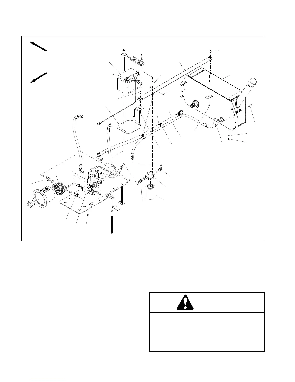
Figure 7
1. Hydraulic relief valve manifold
2. Flange nut (9 used)
3. Flange head screw (4 used)
4. Hydraulic tank assembly
5. Hose bracket
6. R--clamp (3 used)
7. R--clamp (3 used)
8. 45
o
hydraulic fitting (2 used)
9. Hydraulic hose
10. Filter head
11. Hydraulic hose
12. Flange nut (4 used)
13. Oil filter
14. Cap screw (2 used)
15. Straight hydraulic fitting
16. Hydraulic gear pump
17. Straight hydraulic fitting
18. Battery tray
19. Battery
20. O--ring
21. #6 plug
22. Flange head screw (7 used)
9
11
4
19
5
18
6
7
2
16
8
10
13
22
15
1
14
17
3
22
22
12
8
2
2
2
21
20
FRONT
RIGHT
Removal (Fig. 7)
1. Position machine on a level surface. If ProPass is at-
tached to tow vehicle, apply tow vehicle parking brake,
stop engine and remove key from the ignition switch.
Chock wheels to prevent ProPass machine from mov-
ing.
2. Read the General Precautions for Removing and
Installing Hydraulic System Components in the Service
and Repairs section of Chapter 3 -- Hydraulic System.
CAUTION
Before disconnecting any hydraulic compo-
nents, operate all hydraulic controls to relieve
system pressure and avoid injury from pressur -
ized hydraulic oil. See Relieving Hydraulic Sys-
tem Pressure in the General Information section
of Chapter 3 -- Hydraulic System.