ProPass 200Page 5 -- 10Chassis
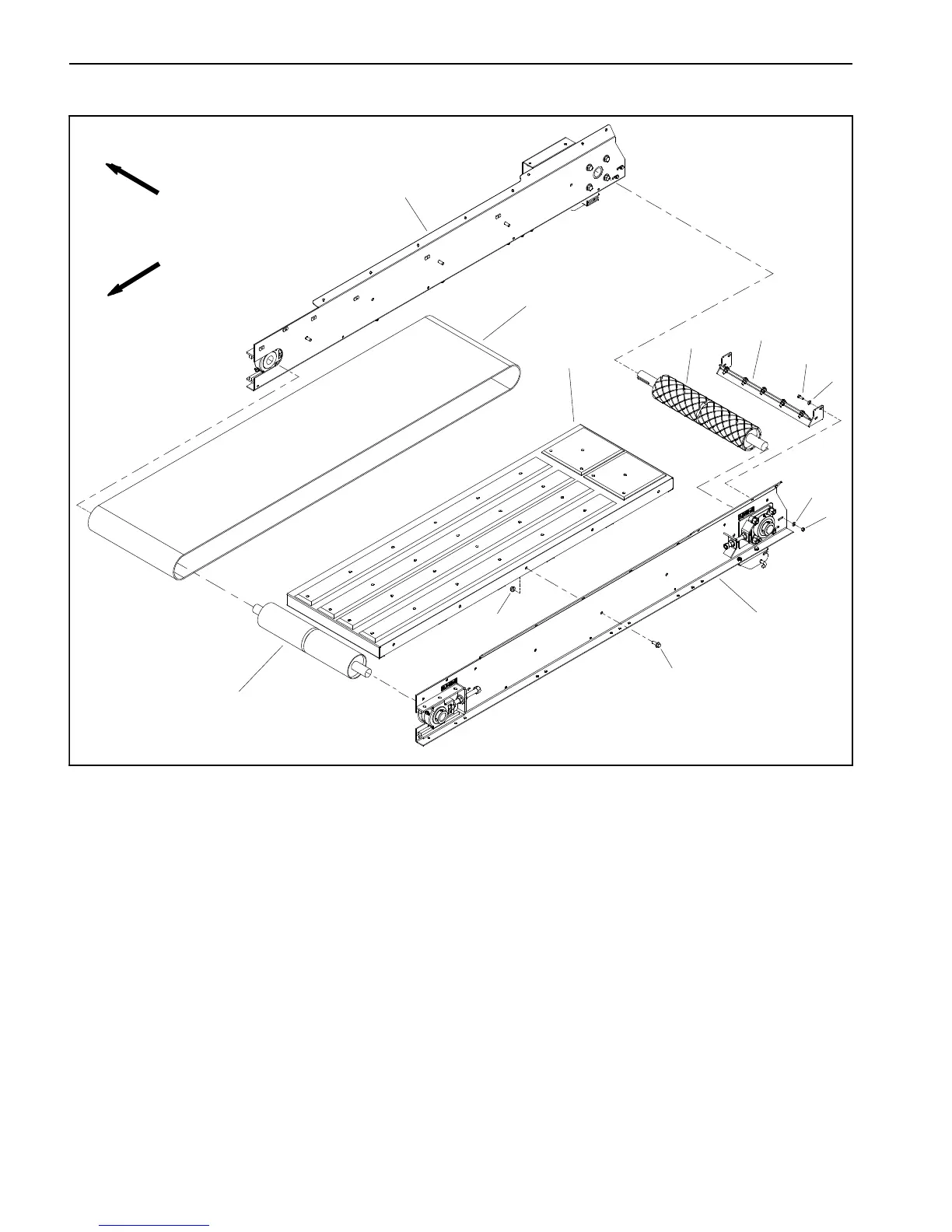
Floor Conveyor Belt
Figure 10
1. LH conveyor frame ass embly
2. Conveyor bed assembly
3. RH conveyor frame assembly
4. Floor conveyor belt
5. Idler roller
6. Drive roller
7. Scraper assembly
8. Cap screw (4 used)
9. Flat washer (8 used)
10. Lock nut (4 used)
11. Flange head screw (10 used)
12. Flange nut (10 used)
2
6
3
9
5
1
4
7
8
10
11
12
9
FRONT
RIGHT
To remove and replace the floor conveyor belt, removal
of the left side conveyor frame is recommended. This
procedure allows the hydraulic motor and drive chain
components to remain in place on the right side convey-
or frame.
Removal (Fig. 10)
1. Position machine on a level surface. If ProPass is at-
tached to tow vehicle, apply tow vehicle parking brake,
stop engine and remove key from the ignition switch.
Chock wheels to prevent ProPass machine from mov-
ing.
2. Disconnect electrical power to ProPass machine.
3. Remove rear option assembly (twin spinner or con-
veyor) f rom machine.
4. Remove drive guards, idler guards, bottom guard
and front rinse guard from frame (see Bed Guards in this
section).
5. On both sides of machine, loosen tension on floor
conveyor belt at idler roller shaft (see Drive Roller Bear-
ings in this section).
6. Remove tension on floor drive chain by loosening
cap screw and lock nut on drive chain idler sprocket (see
Floor Motor Drive in this section).