ProPass 200 Page 6 -- 17 Hydraulic Power Pack
Removal (Fig. 9)
1. Position machine on a levelsurface.IfProPassisat-
tached to tow vehicle, apply tow vehicle parking brake,
stop engine and remove key from the ignition switch.
Chock wheels to prevent ProPass machine from mov-
ing.
2. Read the General Precautions for Removing and
Installing Hydraulic System Components in the Service
and Repairs section of Chapter 3 -- Hydraulic System.
CAUTION
Before disconnecting any hydraulic compo-
nents, operate all hydraulic controls to relieve
system pressure and avoid injury from pressur-
ized hydraulic oil. See Relieving Hydraulic Sys-
tem Pressure in the General Information section
of Chapter 3 -- Hydraulic System.
3. Thoroughly clean junction of hydraulic lines and gear
pump fittings. Disconnect h ydraulic lines from gear
pump. Install caps or plugs in hose, tube and pump fit-
tings to prevent contamination and leakage of hydraulic
oil.
4. Support gear pump to prevent it from falling during
removal.
5. Remove two (2) cap screw s and flat washers that se-
cure pump to flange adapter.
6. Slide gear pump from spider coupling a nd remove
pump (with coupling jaw attached) from the machine.
IMPORTANT: To prevent damage to hydraulic
pump, DO NOT hit coupling jaw or pump shaft with
a hammer during coupling jaw removal or installa-
tion.
7. Loosen set screw that secures coupling jaw to gear
pump shaft. Use puller to remove coupling jaw from
shaft. Locate and retrieve key from pump shaft.
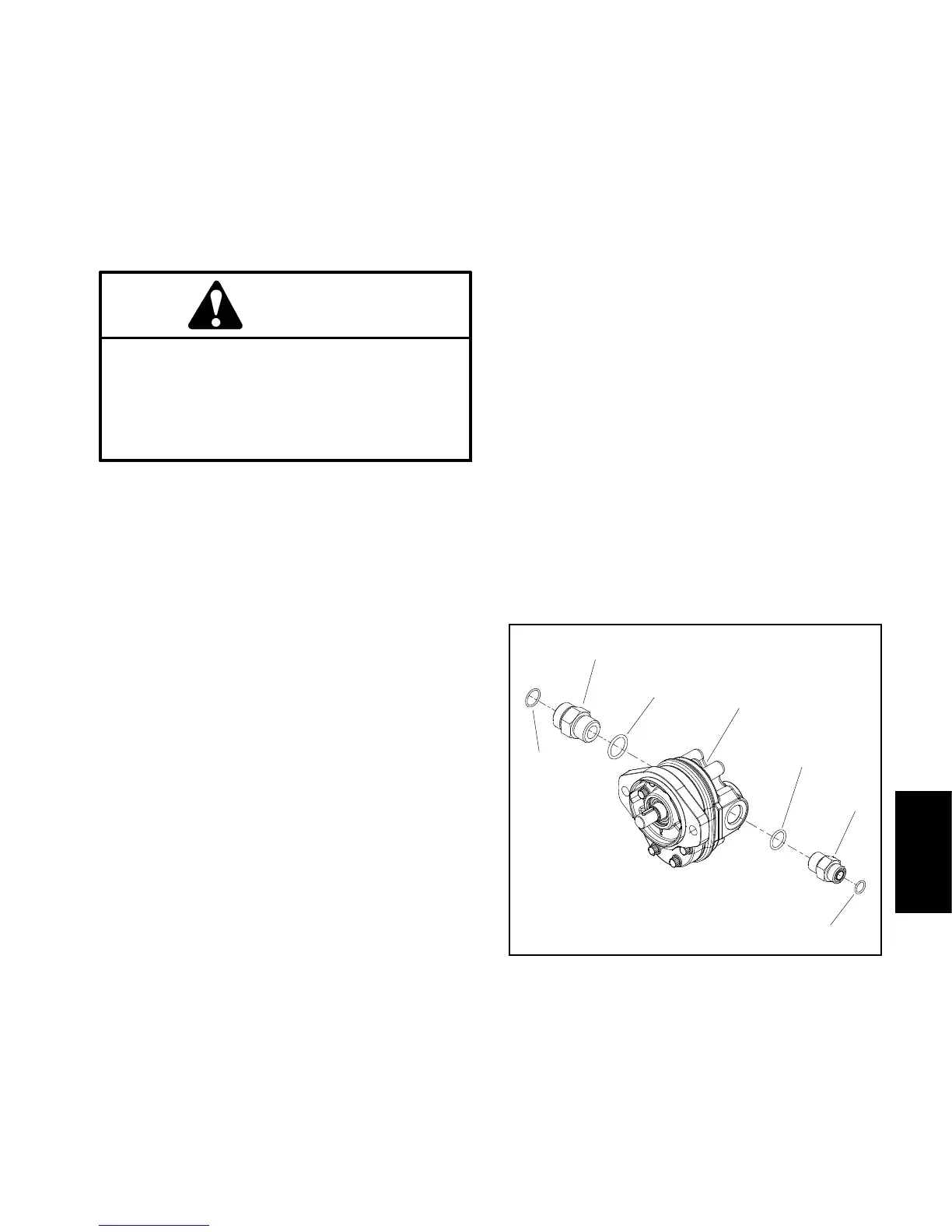
8. If necessary, remove fittings from pump and discard
fitting O--rings (Fig. 10).
Installation (Fig. 9)
1. If fittings were removed from gear pump, lubricate
and place new O--rings onto fittings (Fig. 10). Install and
tighten fittings into pump ports (see Hydraulic Fitting
Installation in the General Information section of
Chapter 3 -- Hydraulic System).
2. Install key to the pump shaft. Apply antiseize lubri-
cant to gear pump shaft.
3. Slide coupling jaw fully onto pump shaft. Apply Loc-
tite #242 (or equivalent) to coupling jaw set screw. Se-
cure coupling jaw to pump shaft with set screw.
4. Make sure that spider coupling (item 26) is posi-
tioned into coupling jaw on engine shaft.
5. Align c oupling jaw on pump shaft with spider coup-
ling in engine coupling jaw. Insert coupling jaw on pump
shaft into spider coupling and align gear pump mounting
holes with flange adapter holes.
6. Secure gear pump to flange adapter with two (2) cap
screws and flat washers.
7. Remove plugs from hydraulic hose, tube and pump
fittings. Connect hydraulic lines to gear pump (see Hy -
draulic Hose and Tube Installation in the General Infor-
mation section of Chapter 3 -- Hydraulic System).
8. Check oil level in the hydraulic tank and add correct
oil if necessary.
9. Start the engine and operate at idle speed until air is
outofhydraulicsystem.
10.Stop the engine and recheck oil level in tank. Add
correct oil if necessary.
1. Gear pump
2. O--ring
3. Hydraulic fitting
4. O--ring
5. O--ring
6. Hydraulic fitting
7. O--ring
Figure 10
2
1
3
4
5
6
7
Hydraulic
Power Pack