GX9 ASD Installation and Operation Manual 17
Connecting the ASD
Contact With 3-Phase Input/Output Terminals May Cause An Electrical Shock
Resulting In Injury Or Loss Of Life.
Refer to the section titled Installation Precautions on pg. 4 and the section titled Lead Length
Specifications on pg. 19 before attempting to connect the ASD and the motor to electrical power.
Power Connections
See Figure 19 on pg 30 for a system I/O connectivity schematic.
R/L1, S/L2, and T/L3 are the 3-phase input supply terminals for the ASD.
U/T1, V/T2, and W/T3 are the output terminals of the ASD that connect to the motor.
Connect the input and output power lines of the ASD as shown in Figure 4 on pg 18.
An inductor (DCL) may be connected across the PO and PA/+ terminals to provide additional filtering.
When not used, a jumper must be connected across these terminals.
PA/+ and PB are used for the DBR connection if using a braking resistor.
PC/- is the negative terminal of the DC bus.
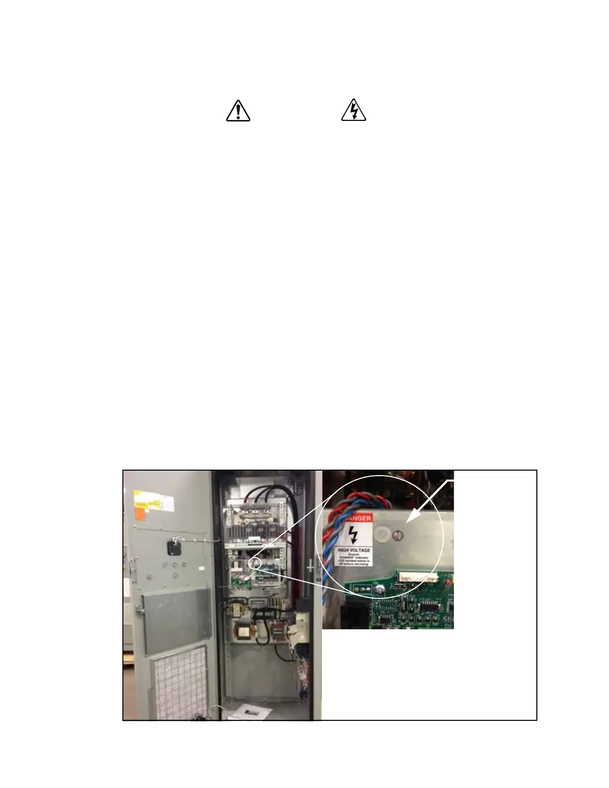
The Charge Indicator LED provides an indication that there is a harmful voltage level present. The
location of the Charge Indicator LED is shown in Figure 3.
Ensure that the Charge Indicator LED is off before coming into contact with any circuits or attempting
to perform any maintenance on the ASD.
Note: The GX9610K is shown in figure 3 below. See the drawings of the system received for
the actual location of the Charge LED.
Figure 3. Typical GX9 ASD Charge Indicator LED.
 Loading...


