GX9 ASD Installation and Operation Manual 71
Virtual Linear Pump Setup
Toshiba International Corporation’s Virtual Linear Pump algorithm allows for direct and precise
control of pressure, flow rate, or level. This is achieved without the concerns, instabilities, or
complexities that are traditionally associated with pumping system control. This section provides useful
setup and operational information for the Virtual Linear Pump system.
The system is initially configured using the (Program Virtual Linear Pump Setup Wizard. Once
the Wizard is started it must be completed for normal Virtual Linear Pump operations to function.
However, the parameters addressed while using the Wizard or the Virtual Linear Pump Settings menu
selection are also accessible via their associated direct access numbers for specific adjustments when
required (see pg. 75).
If using direct access numbers or the Virtual Linear Pump Settings to configure the Virtual Linear
Pump algorithm, parameter F911 must first be set to 255:Virtual Linear Pump to accept the new or
changed Virtual Linear Pump parameter settings. Upon completion of the parameter changes, set
parameter F911 to 1 or 2 to use the changed (or new) settings for normal Virtual Linear Pump
operations (Zero may be selected at F911 to save the changes to be used later).
The setup procedure and the Wizard setup screens are shown below.
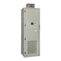
Figure 28. Input the Electrical Specifications of the Motor.
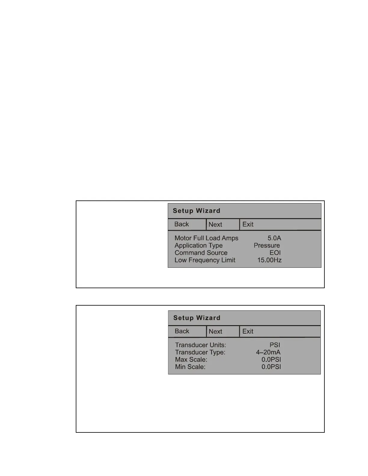
Figure 29. Input the Specifications of the Transducer.
tup Wizard
1.From the nameplate of the
motor, enter the FLA.
2.Select Pressure, Flow, or
Level.
3.Select the command source;
EOI, VI/II, RR, Com. Opt.
4.Set the Low Frequency
Limit. 15 Hz fits most appli-
cations.
5.Click Next to continue.
6.Set the unit of measure for
the transducer; pressure,
flow rate, or level (i.e., PSI,
GPM, Inches of Water
Column, Feet of Water
Column, or Cubic Feet per
Minute, °C, °F, or Custom).
7.Select the transducer output
signal type; current or
voltage and the range.
8.Set the maximum reading of
the transducer.
9.Set the minimum reading of
the transducer.
10.Click Next to continue.
Note: The Custom selection allows for a user-
created unit of measure for the process
variable as measured by the
transducer.
 Loading...


