28 GX9 ASD Installation and Operation Manual
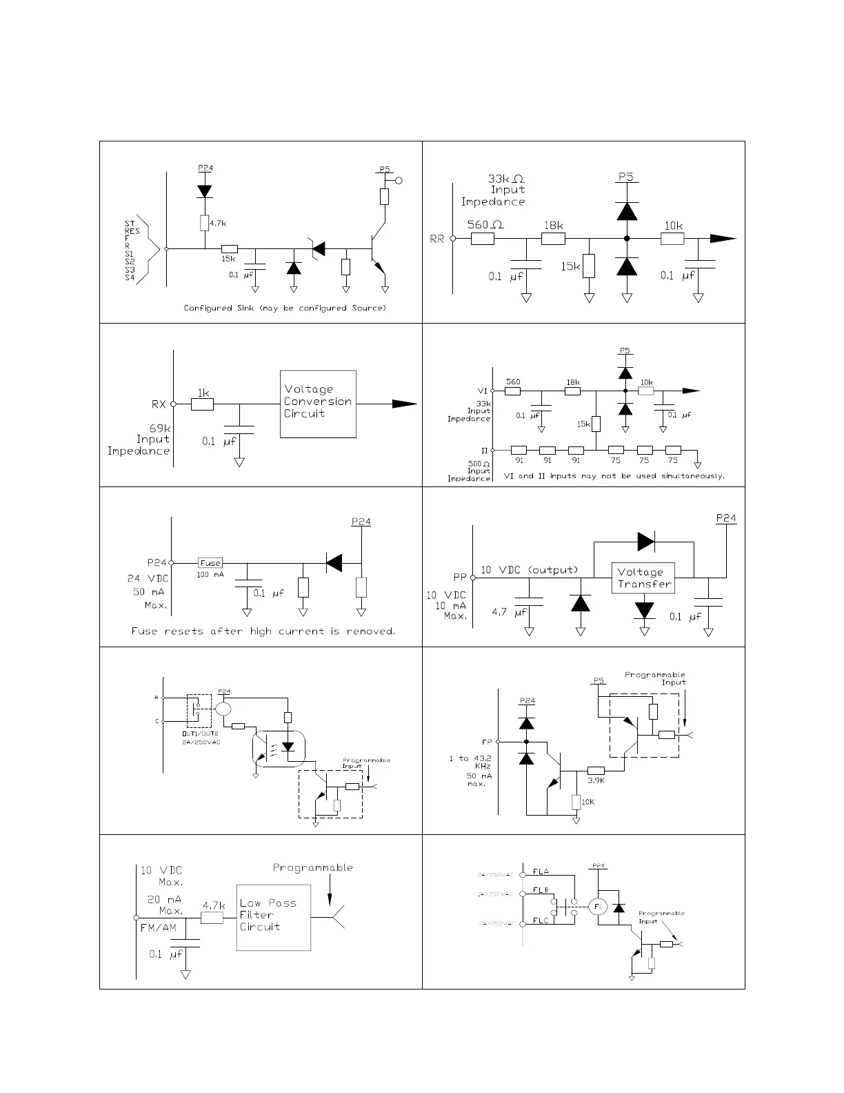
I/O Circuit Configurations
Figure 9. Discrete Input. Figure 10. RR Input.
Figure 11. RX Input. Figure 12. VI/II Input.
Figure 13. P24 Output. Figure 14. PP Output.
Figure 15. OUT1/OUT2 Output. Figure 16. FP Output.
Figure 17. AM/FM Output. Figure 18. Fault Relay (during fault).
 Loading...


