20 GX9 ASD Installation and Operation Manual
I/O and Control
The GX9 ASD can be controlled by several input types and combinations thereof, as well as operate
within a wide range of output frequency and voltage levels. This section discusses the ASD control
methods and supported I/O functions.
The Terminal Board supports discrete and analog I/O functions and is shown in Figure 6 on pg 24.
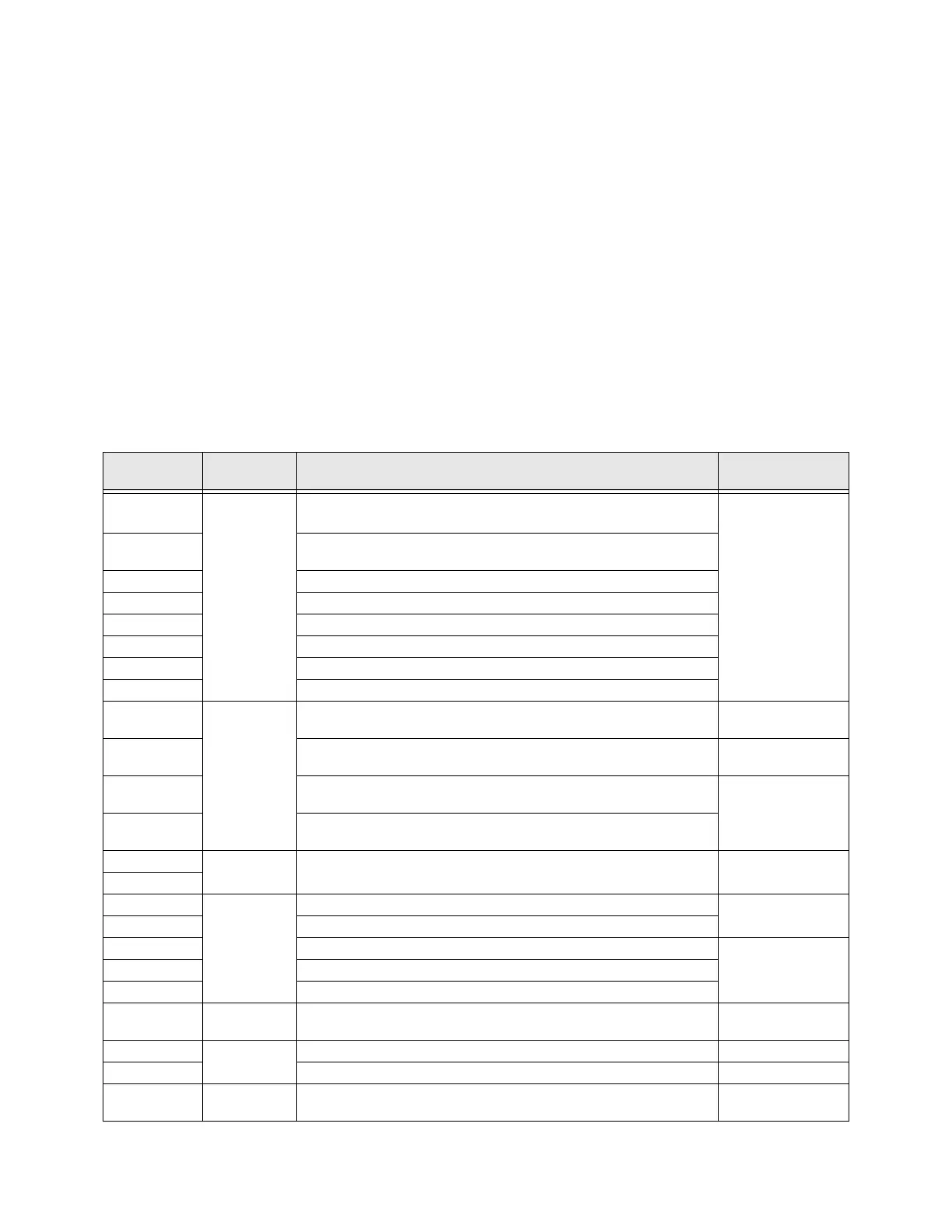
Table 2 lists the names and the default settings of the input and output terminals of the Terminal Board.
See the section titled Terminal Descriptions on pg. 21 for an expanded description of each terminal.
Note: Set the Command Mode to Terminal Board to use the input control lines of the
Terminal Board for command input (Program Fundamental Standard Mode
Selection Command Mode Terminal Board). Output lines of the Terminal
Board need not be selected to enable the output. However, output lines will have to be
set to a specific function (see Table 10 on pg. 222).
Figure 19 on pg 30 shows the typical connection diagram for the GX9 ASD system.
Table 2. Terminal Board Terminal Names and Functions.
Default Term.
Setting
Input/Output
Default Function
(also see
Terminal Descriptions on pg. 21
)
Circuit Config.
ST
Discrete Input
Connect to CC
to activate
(Sink mode)
Sink/Source
switching
applies to
discrete input
terminals only.
Standby — Multifunctional programmable discrete input. Activation
required for normal ASD operation.
Figure 9 on pg 28.
RES
Reset — Multifunctional programmable discrete input. Resets a faulted
ASD.
F
Forward — Multifunctional programmable discrete input.
R
Reverse — Multifunctional programmable discrete input.
S1
Preset Speed 1 — Multifunctional programmable discrete input.
S2
Preset Speed 2 — Multifunctional programmable discrete input.
S3
Preset Speed 3 — Multifunctional programmable discrete input.
S4
Emergency Off — Multifunctional programmable discrete input.
RR
Analog Input
RR — Multifunction programmable analog input
(0.0 to 10 volt input — 0 to 80 Hz output).
Figure 10 on pg 28.
RX
RX — Multifunctional programmable analog input
(-10 to +10 VDC input — -80 to +80 Hz output).
Figure 11 on pg 28.
II
II — Multifunctional programmable analog input (4 [0] to 20 mADC
input — 0 to 80 Hz output). Return at II(-).
Figure 12 on pg 28
VI
VI — Multifunctional programmable analog input
(0 to 10 VDC input — 0 to 80 Hz output).
AM
Analog Output
Produces an output current that is proportional to the magnitude of the
function assigned to this terminal.
Figure 17 on pg 28
FM
OUT1 (C-A)
Switched
Output
Low Frequency — Programmable contact (N.O.).
Figure 15 on pg 28
OUT2 (C-A)
Reach Frequency — Programmable contact (N.O.).
FLA
Fault relay (N.O.).
Figure 18 on pg 28
FLB
Fault relay (N.C.).
FLC
Fault relay (Common).
FP
Pulsed Output
Frequency Pulse — an output pulse train that has a frequency which is
based on the output frequency of the ASD.
Figure 16 on pg 28
P24
DC Output
24 VDC @ 50 mA output. Figure 13 on pg 28
PP
PP — 10.0 VDC voltage source for the external potentiometer. Figure 14 on pg 28
CC
— Return for analog and discrete input terminals.
DO NOT connect to
Earth Gnd.
 Loading...


