30 GX9 ASD Installation and Operation Manual
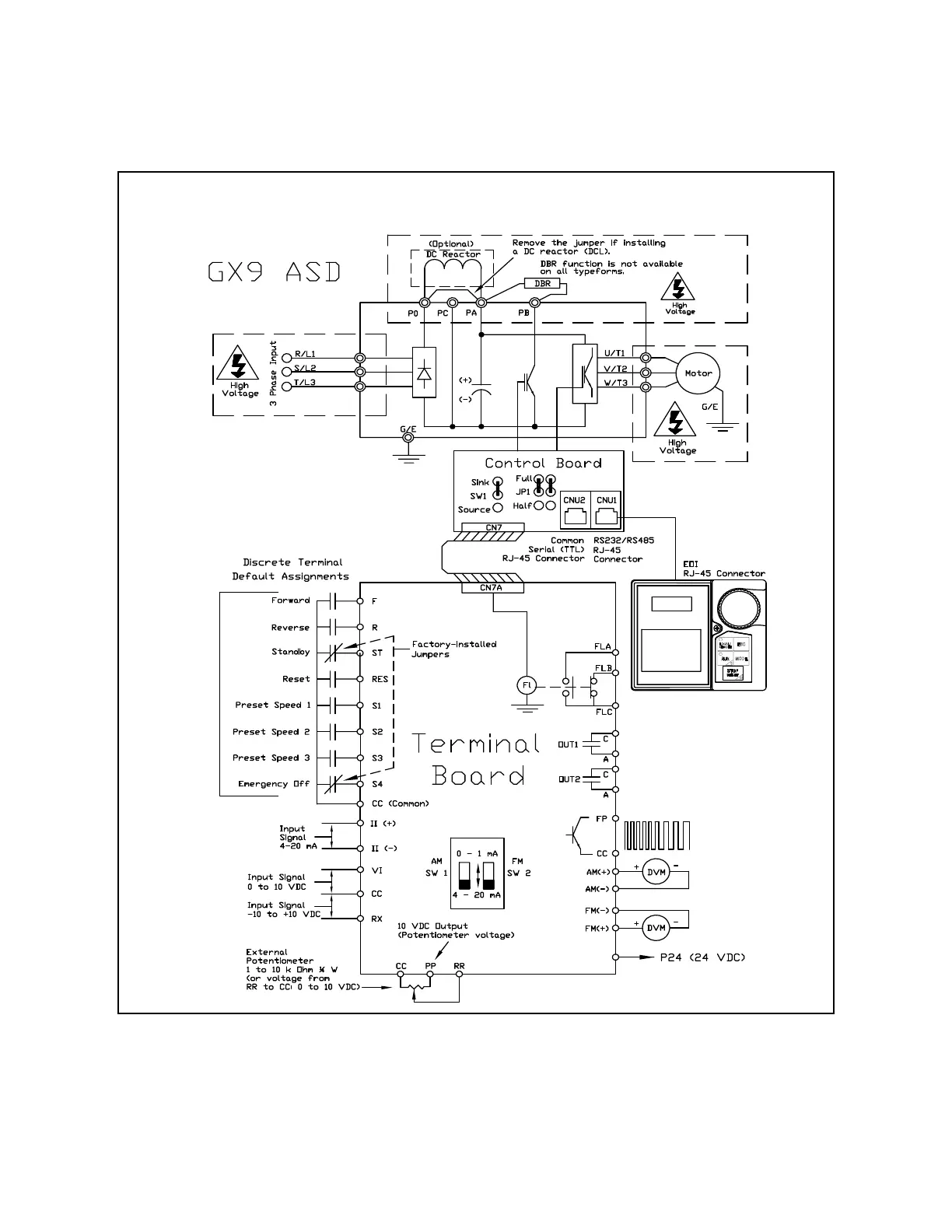
Typical Connection Diagram
Figure 19. GX9 ASD Typical Connection Diagram.
Note: The VI, RX, and RR analog input terminals are referenced to CC.
The AM, FM, and II analog input terminals are referenced to the respective negative
terminals. The FP, PP, and P24 output terminals are referenced to CC.
Note: See alternative ST-to-CC activation configuration on pg. 16.
Note: When connecting multiple wires to the PA, PB, PC, or PO terminals, do
not connect a solid wire and a stranded wire to the same terminal.
 Loading...


