72 GX9 ASD Installation and Operation Manual
WARNING! — THE FOLLOWING STEP WILL START THE MOTOR!
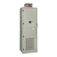
Figure 30. Set the Maximum Threshold Value.
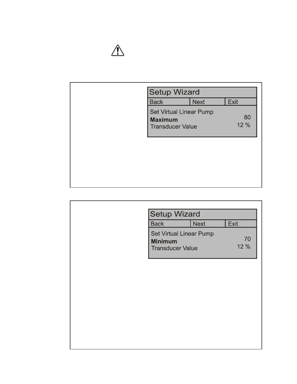
Figure 31. Set the Minimum Threshold Value.
11. Set the system for normal flow
and ensure that all system valves
are set for normal operation.
12. Place the system in the Local
mode and press the Run key.
13. Click Next to continue.
The Motor/Pump combination
capacity is automatically
calculated and displayed as the Maximum threshold. Normally, no further adjustment is
required for the Maximum threshold setting.
The Maximum threshold value may be adjusted, if required, at F918. The Maximum
threshold setting (F918) minus the F933 setting comprises the range of the Maximum
threshold zone.
14. Click Next to continue.
Maximum Threshold Zone
15. The Minimum threshold value
setting is typically above the
electrical stall of the motor,
above the minimum system
pressure, above the manual
change plateau, and well below
the typical operating point of the
system.
Click in the Minimum threshold
field and, using the Rotary
Encoder, slowly decrease the Minimum threshold value while observing the LED
display.
If either of the conditions listed below should occur while decreasing the Minimum
threshold value, increase the Minimum threshold number until the condition is no longer
true to set the Minimum threshold:
• The motor stalls,
• The output frequency is greater than the setting of F505, or
• The output frequency no longer changes with continued Virtual Linear Pump number
changes.
The Minimum threshold setting (F917) plus the F919 setting comprises the range of the
Minimum threshold zone.
Minimum Threshold Zone
 Loading...


