Instructions for mounting / schematic
TR-Electronic GmbH 2007, All Rights Reserved Printed in the Federal Republic of Germany
Page 40 of 51 TR-ELA-BA-DGB-0004 v16 03/17/2021
4 Instructions for mounting / schematic
Before mounting TR-linear-Transducer, make sure there are no strong magnetic and
electric interference fields in the vicinity.
Inadmissible interference fields can influence the measuring precision. The field
strength may be max. 3 mT in the vicinity of the measuring rod.
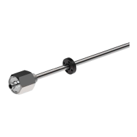
4.1 Mechanics rod housing design
The measurement is one coupled contactlessly about the magnetic field of the position
sensor on the sensor rod. The precision of the measurements is among others addicted
to the balance of magnetic field geometry. This means for the mechanics, that the
position sensor has to be led centrically add-only and axially parallel to the rod precisely.
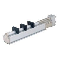
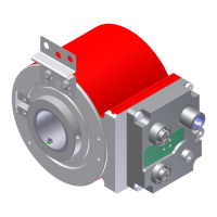
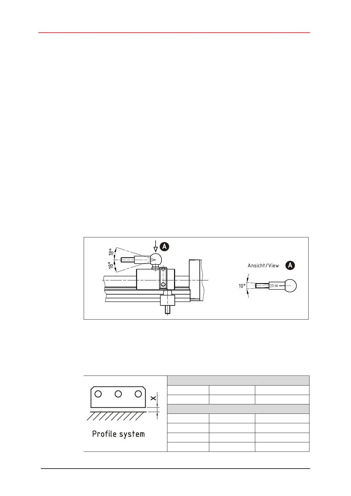
4.2 Mechanics profile- housing design
Since the position sensor by the measuring body mechanically one leads, is relatively
simple the installation the TR-linear-Transducer system. The exact guidance of the
captive-sliding magnet and non-contact and wear free measurement system each
other optimally. In order to reduce the wear between captive-sliding magnet and
measuring body to a minimum, the dimensional tolerances for angle and parallel
disalignment must be absolutely kept:
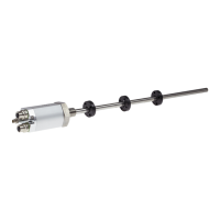
The exact of the measured value depends also on the symmetry of magnetic field
geometry. If no captive-sliding magnet is used, the position sensor must be led exactly
in axial direction to the measuring body. The admissible maximum distance between
position sensor and measuring body may not be exceeded:
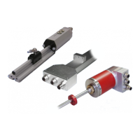
Distinction: