103
3. When the lever is depressed, the meter must read
continuity. When released, the meter must read show
OFL.
NOTE: If the meter readings are not as described,
replace the switch.
VOLTAGE (Headlight)
1. Connect the red meter lead to the white wire; then
connect the black meter lead to the black wire.
2. Turn the ignition switch to the ON position and the
headlight switch to the low-beam position (C). The
meter must show battery voltage.
PK021A
NOTE: If the meter does not show battery voltage,
troubleshoot the 10-amp LO-BEAM fuse on the
power distribution module, the headlight switch,
main relay, 30-amp MAIN fuse, 10-amp LIGHTS fuse
or the main harness.
3. Connect the red meter lead to the yellow/black wire;
then select the high beam (D) position on the head-
light switch. The meter must show battery voltage.
NOTE: The battery voltage will show lower in steps
2 and 3 due to electrical loading of the headlights.
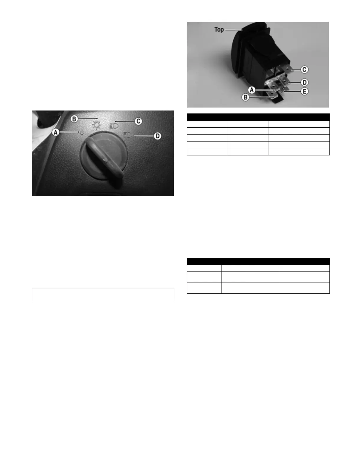
RESISTANCE (Drive Select)
1. Remove the instrument gauge from the switch panel;
then remove the four cap screws securing the switch
panel to the dashboard. Disconnect the switches.
2. Using an ohmmeter, the following readings must be
observed:
PR566A
VOLTAGE (Drive Select)
NOTE: Voltage tests must be made with the switch
and the actuator connected. The meter leads can be
connected at the back of the drive select switch using
a break-out harness or MaxiClips. The front drive
actuator connector must be connected. The connector
can be accessed by removing the front skid plate.
1. Connect the black tester lead to the black wire; then
turn the ignition switch to the ON position.
2. Select the DC Volts position on the tester and
observe the meter readings for each of the three
switch positions. BV represents approximately bat-
tery voltage.
NOTE: If the meter does not show voltages accord-
ing to the chart, make sure the front drive actuator is
plugged in; then troubleshoot the switch, 10-amp
power fuse, main relay, main fuse, battery connec-
tions, or wiring harness.
VOLTAGE (Reverse Override)
NOTE: To perform the following tests, the ignition
switch must be in the ON position and the transmis-
sion shifted into reverse gear.
1. Remove the dash mounted switch panel. Connect the
red meter lead to the red/green wire and the black
meter lead to the black wire; then select 2WD on the
drive select switch. The meter must show battery
voltage.
2. Depress the reverse override switch. The meter must
show near zero volts.
3. Select 4WD on the drive select switch. The meter
must show battery voltage.
Component data can be retrieved using the Dealer Diag-
nostic Service. Utilize the Sensor Data screen.
2WD 4WD DIFFERENTIAL LOCK
A to D <1 ohm A to D <1 ohm A to D <1 ohm
C to E 51 ohms C to E 51 ohms C to E 51 ohms
A to B Open A to B <1 ohm A to B <1 ohm
A to C Open A to C Open A to C 51 ohms
A to E Open A to E Open A to C <1 ohm
WIRE COLOR 2WD 4WD DIFFERENTIAL LOCK
Red to Orange 12.0 DC Volts 12.0 DC Volts 12.0 DC Volts
Red to White/
Green
11.5 DC Volts 0 DC Volts 0 DC Volts
Red to White/
Orange
11.5 DC Volts 11.5 DC Volts 0 DC Volts
 Loading...