86
Joining Crankcase Halves
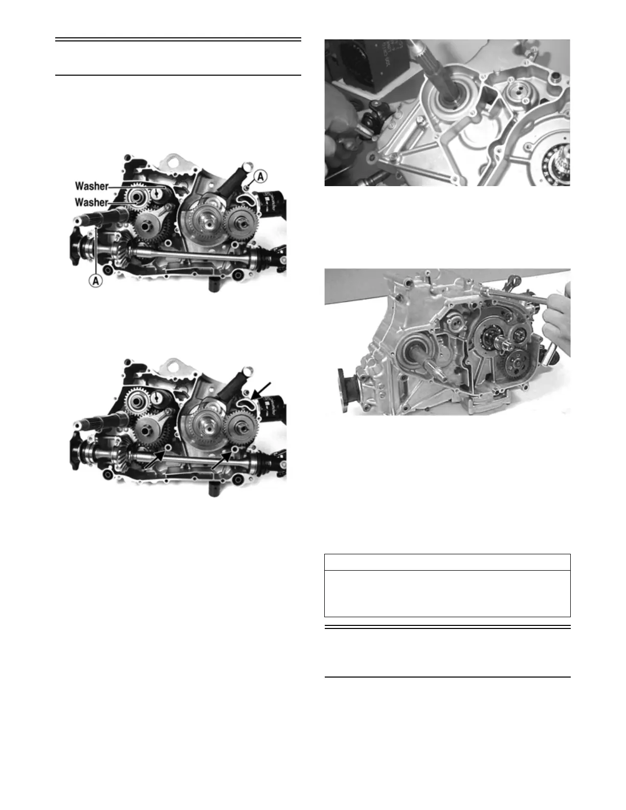
1. Verify that the two alignment pins (A) are in place
and that both case halves are clean and grease free.
Apply Loctite #5900 or suitable substitute sealant to
the mating surfaces. Place the left-side half onto the
right-side half.
FI639B
NOTE: Be sure to apply silicone to the inside radius
of all cap screw locations and the entire surface of the
internal cap screw bosses.
FI639D
2. Using a plastic mallet, lightly tap the case halves
together until cap screws can be installed.
3. From the right side, install the crankcase cap screws
noting the location of the different-sized cap screws;
then tighten only until snug.
NOTE: Rotate the shafts back and forth to ensure
no binding or sticking occurs while tightening the cap
screws.
MD1008
4. From the left side, install the remaining crankcase
cap screws; then tighten only until snug.
NOTE: Rotate the shafts back and forth to ensure
no binding or sticking occurs while tightening the cap
screws.
CC871
5. In a crisscross pattern, tighten the 8 mm cap screws
until the halves are correctly joined; then tighten to
21 ft-lb (28.6 N-m).
NOTE: Rotate the shafts back and forth to ensure
no binding or sticking occurs.
6. In a crisscross pattern, tighten the 6 mm cap screws
to 10 ft-lb (13.6 N-m).
NOTE: Rotate the shafts back and forth to ensure
no binding or sticking occurs.
Installing Engine/
Transmission
NOTE: The manufacturer recommends new gas-
kets, patch-lock cap screws, lock nuts, and O-rings be
installed whenever servicing the vehicle.
AT THIS POINT
After completing center crankcase components, pro-
ceed to Installing Right-Side Components, to Installing
Left-Side Components, and to Installing Top-Side Com-
ponents.