102
Switches
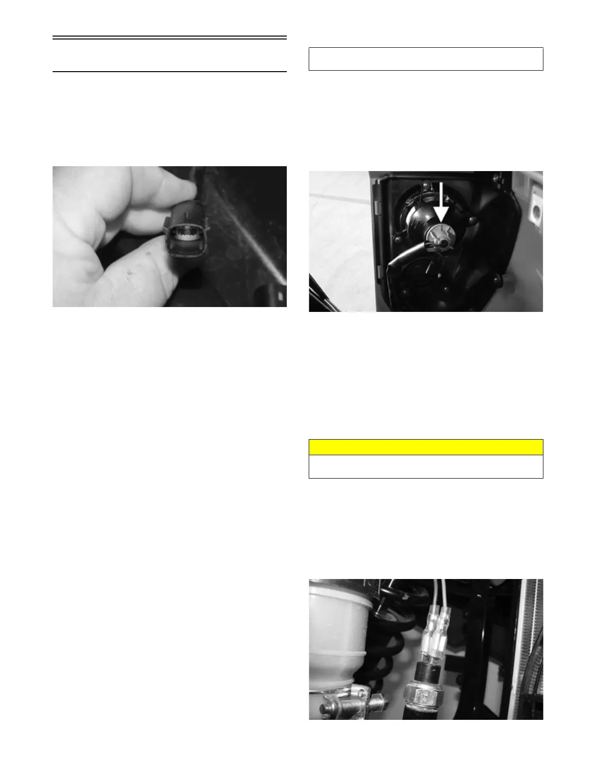
SEAT BELT LIMITER SWITCH
1. Remove the passenger seat. Locate the switch con-
nector on the driver’s side; then disconnect.
2. Buckle the driver’s seat belt. On the switch side, con-
nect one meter lead to one pin and the other meter
lead to the opposite connector pin.
HDX374
3. The meter should read less than one ohm.
4. Release the seat belt latch from the buckle while the
meter leads are connected to the pins. Meter reading
should show OFL.
NOTE: If the meter readings are OFL or greater
than one ohm with the seat belt buckled, replace the
buckle switch assembly. If the resulting readings from
step 4 are not OFL, replace the buckle switch assem-
bly.
VOLTAGE (Taillight)
NOTE: The ignition switch must be in the ON posi-
tion.
1. Set the meter to the DC Voltage position. Disconnect
the connector from the back of the taillight assembly.
2. Connect the red tester lead to the white/red wire and
the black tester lead to the black wire.
3. With the headlight switch in the running, low and
high beam positions, the meter should read approxi-
mately battery voltage.
NOTE: If the meter shows no battery voltage, trou-
bleshoot the main wiring harness, 10-amp LIGHTS
fuse, headlight switch or the battery.
NOTE: If the meter shows battery voltage, the main
wiring harness and related components are good; pro-
ceed to checking the bulb.
VOLTAGE (Brake Light)
NOTE: The ignition switch must be in the ON posi-
tion.
1. Set the meter selector to the DC Voltage position.
Disconnect the connector from the back of the tail-
light assembly.
2. Connect the red tester lead to the red/blue wire and
black tester lead to the black wire.
PK328
3. Depress and hold the brake pedal. The meter must
show battery voltage.
NOTE: If the meter shows no battery voltage, trou-
bleshoot the main wiring harness, switch, fuse or the
battery.
NOTE: If the meter shows battery voltage, the main
wiring harness and related components are good. Pro-
ceed to check the bulb.
RESISTANCE (Brake Light)
NOTE: The brake pedal must be depressed for this
test.
1. Set the meter selector to the OHMS position.
Remove both wires from the switch.
2. Connect the red tester lead to one terminal spade;
then connect the black tester lead to the other termi-
nal spade.
PK292
Component data can be retrieved using the Dealer Diag-
nostic Service. Utilize the Sensor Data screen.
CAUTION
Always disconnect the battery when performing resis-
tance tests to avoid damaging the multimeter.