66
FI539
12. Install the water pump cover with a new O-ring and
secure with the four cap screws. Tighten to 8 ft-lb
(10.9 N-m).
FI538
13. Connect the coolant hoses to the water pump and
secure with the hose clamps. Tighten securely.
Left-Side Components
NOTE: For efficiency, it is preferable to remove and
disassemble only those components which need to be
addressed and to service only those components. The
technician should use discretion and sound judgment.
NOTE: The engine/transmission does not have to be
removed from the frame for this procedure.
Removing Left-Side
Components
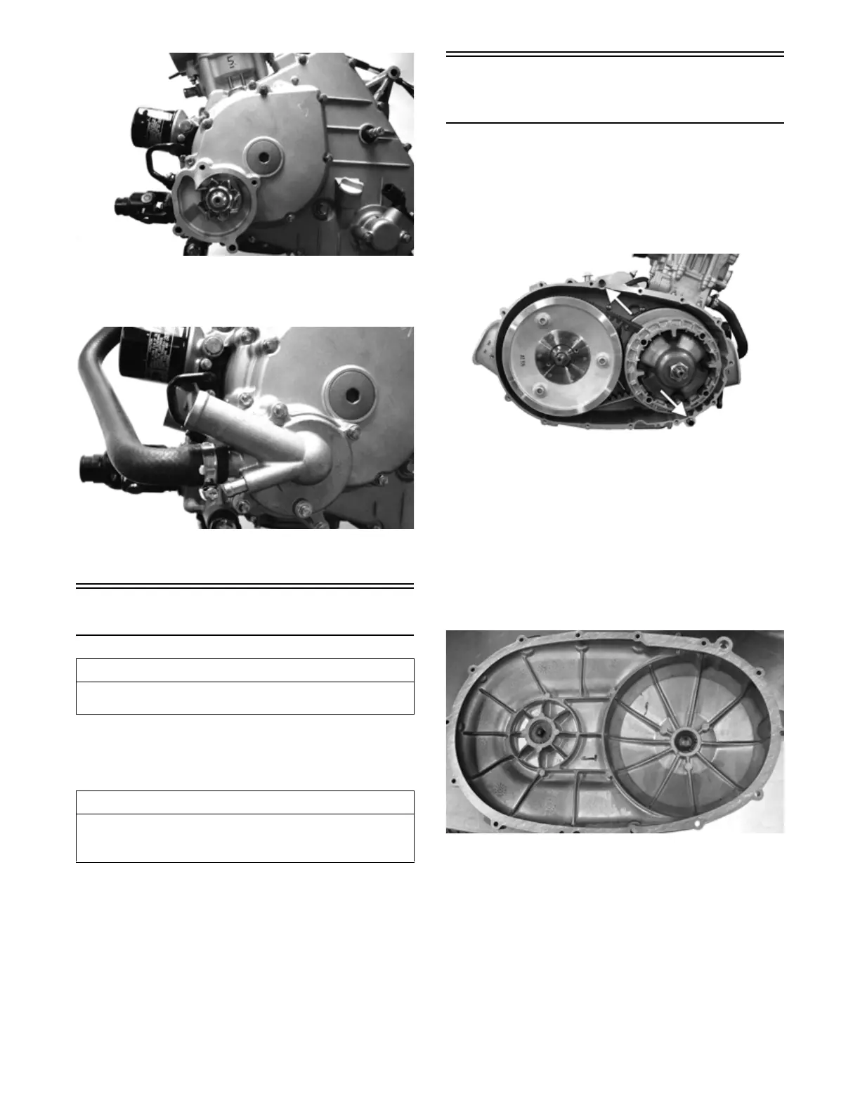
A. V-Belt Cover
B. Driven Pulley
C. Clutch Cover
1. Remove the cap screws securing the V-belt cover to
the clutch cover; then remove the V-belt cover.
Account for two alignment pins and a gasket.
FI721A
2. Inspect the bearings and input shaft bearing seals in
the outer CVT cover. Rotate the inner races; if they
do not rotate smoothly they must be replaced.
Remove the snap ring and seal (secondary input shaft
only); then using a suitable sized blind hole bearing
puller, remove the bearing. Using a bearing driver
the same size as the outside diameter of the outer
race of the bearing, drive the new bearing into the
CVT cover. Install a new snap ring and seal (second-
ary input shaft only).
FI724
3. Mark the movable drive face and the fixed drive face
for installing purposes; then remove the nut holding
the movable drive face onto the crankshaft.
AT THIS POINT
To service center crankcase components only, proceed
to Removing Right-Side Components.
AT THIS POINT
To service any one specific component, only limited dis-
assembly of components may be necessary. Note the
AT THIS POINT information in each sub-section.