105
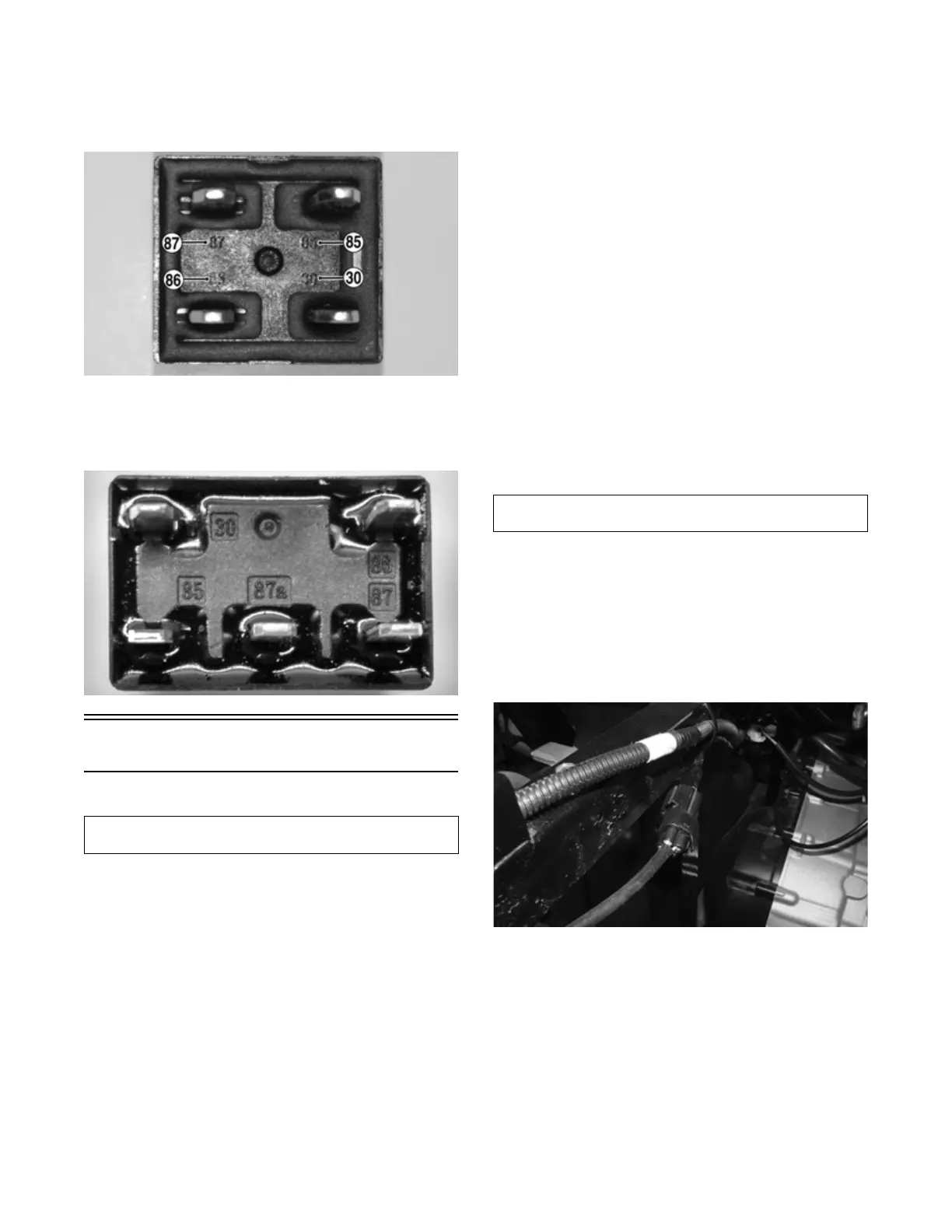
2. Set the meter to the OHMS position. To test the pri-
mary side of the relay, connect the meter leads to the
number 85 and 86 pins. The meter will read approxi-
mately 135 ohms (4-pin relay) or 103 ohms (5-pin
relay).
PK294A
3. Testing Secondary: Using a 9-volt battery, energize
the primary side pins 85 and 86; then test the resis-
tance of the secondary side on the number 87 and 30
pins. The meter should read less than one ohm.
PK295
EFI Sensors/Components
FUEL INJECTOR
Voltage
Remove the connector from the fuel injector. Place the
red meter lead to the orange wire and black meter lead to
ground. With the ignition switch in the on position the
meter must read battery voltage. Place the red meter lead
to the blue wire. The meter must read approximately 4.5
VDC.
Resistance
With the connector still removed from the injector, place
the red meter lead to either terminal of the injector; then
connect the black tester lead to the other terminal. Read-
ing is typically 10.6-15.9 ohms.
NOTE: If voltage is not present, troubleshoot the
battery, connector pins, wiring harness, power fuse,
the main relay, or main fuse. If resistance is not pres-
ent or highly out of specification, replace the injector.
CRANKSHAFT POSITION (CKP)
SENSOR
Resistance
1. Set the meter selector to the OHMS position. Dis-
connect the connector located on the right side of the
engine.
2. Connect the red tester lead to the brown wire; then
connect the black tester lead to the white wire. The
meter reading must be 96-144 ohms.
AC Voltage
NOTE: The battery must be at full charge for these
tests.
1. Set the meter selector to the AC Voltage position.
Disconnect the CKP sensor.
2. On the sensor side of the harness, connect the red
tester lead to the brown wire; then connect the black
tester lead to the white wire.
3. Crank the engine over using the electric starter.
4. The meter reading must be 2.0 volts or more.
OXYGEN (O2) SENSOR
The Oxygen Sensor (O2 Sensor) is located in the exhaust
pipe.
NOTE: When testing the resistance of the sensor’s
heater, the engine/exhaust pipe must be at room tem-
perature (65-75° F) or inaccurate readings will occur.
1. Open the cargo box.
2. Disconnect the sensor.
PK297
NOTE: For this test, the meter must be in OHMS
position.
3. On the sensor side of connector, connect the black test
lead to one white wire pin; then connect the red test
lead to the other white wire pin. Readings should be
between 6.7 and 10.1 ohms.
NOTE: If the meter does not read as specified,
replace the sensor.
Component data can be tested using the Dealer Diag-
nostic Service. Utilize the Test screen.
Component data can be retrieved using the Dealer Diag-
nostic Service. Utilize the Sensor Data screen.