110
PK301
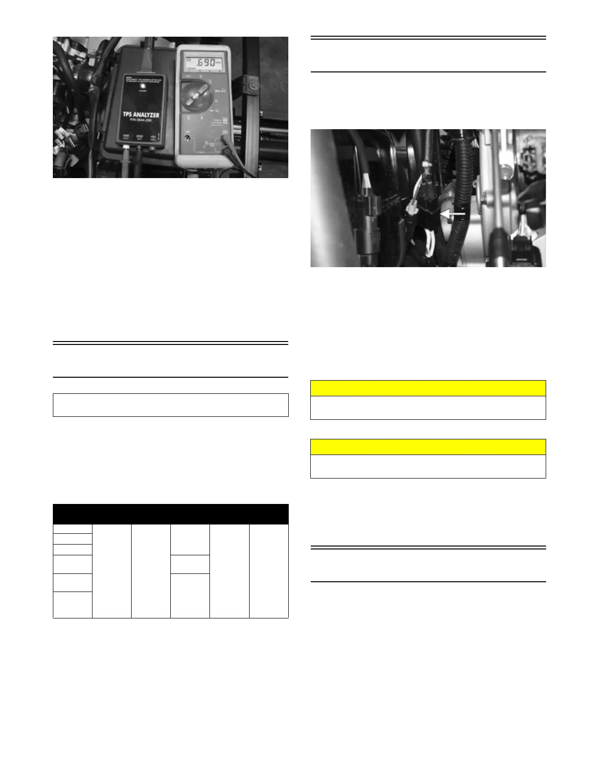
NOTE: If the throttle body, ECM, TPS, or ISC are
replaced, the EFI system must be synchronized. Use
the following procedure:
1. With the key off, depress accelerator pedal to Wide
Open Throttle (WOT).
2. Place the ignition key in the ON position and wait for
10 seconds.
3. Release the accelerator pedal and wait an additional
10 seconds.
4. Turn the key to the OFF position and allow the gauge
to shut off.
RPM Limiter
NOTE: The ROV is equipped with an ECM that
cuts fuel spray and spark when maximum RPM is
approached. When the RPM limiter is activated, it
could be misinterpreted as a high-speed misfire.
NOTE: If the driver’s seatbelt is not fully engaged, vehi-
cle speed will be limited to 15 mph and the seatbelt indi-
cator light will remain illuminated.
Stator Coil
VOLTAGE (AC Generator — No Load)
The black three-pin connector is located on the right side
of the engine.
PK302A
NOTE: Test the connector coming from the engine.
1. Set the meter selector to the AC Voltage position.
2. Test between the three black wires for a total of three
tests.
3. With the shift lever set to neutral and the engine run-
ning at a constant 5000 RPM, all wire tests must be
within specification of approximately 75 VAC.
RESISTANCE (AC Generator)
1. Set the meter selector to OHMS position.
2. Test between the three black wires for a total of three
tests.
3. The meter reading must be less than one ohm.
Regulator/Rectifier
The regulator/rectifier is located on the cross-member of
the frame in the front right fender well. Verify all other
charging system components before the regulator/recti-
fier is replaced.
TESTING VOLTAGE
1. Start engine and warm up to normal operating tem-
peratures; then connect a multimeter (set at the DC
Voltage position) to the battery as follows.
2. Connect the red tester lead to the positive battery
post and the black tester lead to the negative battery
post.
Component data can be retrieved using the Dealer Diag-
nostic Service. Utilize the Sensor Data screen.
Gear Park Neutral Reverse High/Low
Fail-Safe
Mode
2WD
2250 6500
4500
7650 4500
4WD
4WD Lock
2WD
Override
5500
4WD
Override
7000
Differential
-Lock
Override
CAUTION
Do not run the engine at high RPM for more than 10 sec-
onds.
CAUTION
Always disconnect the battery when performing resis-
tance tests to avoid damaging the multimeter.