152
PK234A
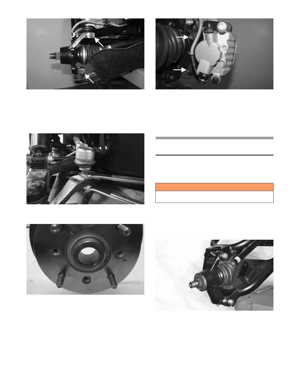
7. Install the tie rod end and secure with the washer
and nut (coated with red Loctite #271). Tighten to
25 ft-lb (34 N-m); then install a new cotter pin and
spread the pin to secure the nut.
NOTE: During assembly, new cotter pins should be
installed.
PK121
8. Apply grease to the hub and drive axle splines; then
install the hub (see Drive System).
PK127
9. Secure the brake caliper holder to the knuckle with
two new “patch-lock” cap screws. Tighten to 19 ft-lb
(25.8 N-m).
PK106B
10. Install the wheels and using a crisscross pattern,
tighten the wheel nuts in 20 ft-lb (27.2 N-m) incre-
ments to a final torque of 45 ft-lb (61.2 N-m) (steel
wheel), 60 ft-lb (81.6 N-m) (aluminum wheel w/black
nuts), or 80 ft-lb (108.8 N-m) (aluminum wheel w/
chrome nuts).
11. Remove the vehicle from the support stand.
Rear A-Arms
REMOVING
1. With the vehicle in park, secure the vehicle on a sup-
port stand to elevate the wheels.
2. Remove the wheel. Remove the cotter pin; then
remove the hub nut to remove the hub.
3. Remove the cap screws and lock nuts securing the
knuckles to the A-arms. Discard the lock nuts.
Account for the dust seals and pivot bushings.
PK284
! WARNING
Make sure the vehicle is solidly supported on the sup-
port stand to avoid injury.