142
PK265
4. Using new patch lock cap screws, install and secure
the rear brake caliper to the mount and tighten the
screws to 19 ft-lb (25.8 N-m). Install the drive axles
(see Drive Axles).
PK266A
5. Remove the fill and check plugs; then add the recom-
mended amount of gear lubricant. Secure the fill and
check plugs.
Hub
REMOVING
1. Secure the vehicle on a support stand to elevate the
wheel; then remove the wheel(s).
NOTE: The jack stands should be placed under the
main frame to avoid contact with front suspension
components.
NOTE: Removing or tightening of the hub nuts
requires the axles be locked. To lock the rear axle,
place the transmission in park. To lock the front axle,
turn the ignition switch to ON and select LOCK on
the drive select switch; then place the transmission in
park and turn the ignition switch to OFF.
2. Remove the cotter pin from the axle. Discard the cot-
ter pins.
PK130
3. Remove the hub nut securing the hub. Continue to
step 4 to remove the front hubs.
4. Remove the brake caliper(s) on the front only.
NOTE: It is not necessary to remove the brake hoses
from the calipers for this procedure.
PK106B
5. Remove the hub assembly.
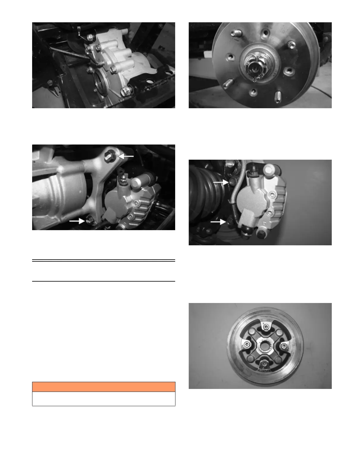
6. Remove the four cap screws (front) or five cap
screws (rear) securing the brake disc to the hub
(front) or input shaft (rear). Discard the bolts.
NOTE: To replace the rear brake disc, the rear gear
case must be removed (see Rear Gear Case).
PK268
! WARNING
Make sure the vehicle is solidly supported on the sup-
port stand to avoid injury.