47
PK178A
PK179A
24. Attach a suitable lifting sling and, with a suitable
engine hoist, slowly lift the engine from the vehicle.
25. Remove the through bolts and lock nuts securing the
front and rear engine brackets to the engine. Discard
the lock nuts.
Servicing Engine
Top-Side Components ................................................ 47
Removing Top-Side Components ............................... 47
Servicing Top-Side Components ................................ 51
Installing Top-Side Components ................................. 56
Right-Side Components ............................................. 60
Removing Right-Side Components ............................ 60
Servicing Right-Side Components.............................. 62
Installing Right-Side Components .............................. 64
Left-Side Components................................................ 66
Removing Left-Side Components............................... 66
Servicing Left-Side Components ................................ 70
Installing Left-Side Components................................. 72
Center Crankcase Components ................................. 76
Separating Crankcase Halves .................................... 76
Disassembling Crankcase Half................................... 77
Servicing Center Crankcase Components.................. 79
Assembling Crankcase Half........................................ 83
Joining Crankcase Halves .......................................... 86
Top-Side Components
NOTE: For efficiency, it is preferable to remove and
disassemble only those components which need to be
addressed and to service only those components. The
technician should use discretion and sound judgment.
NOTE: The engine/transmission does not need to be
removed from the frame for this procedure.
Removing Top-Side
Components
A. Cylinder Head Cover/
Rocker Arms
B. Cylinder Head/Camshaft
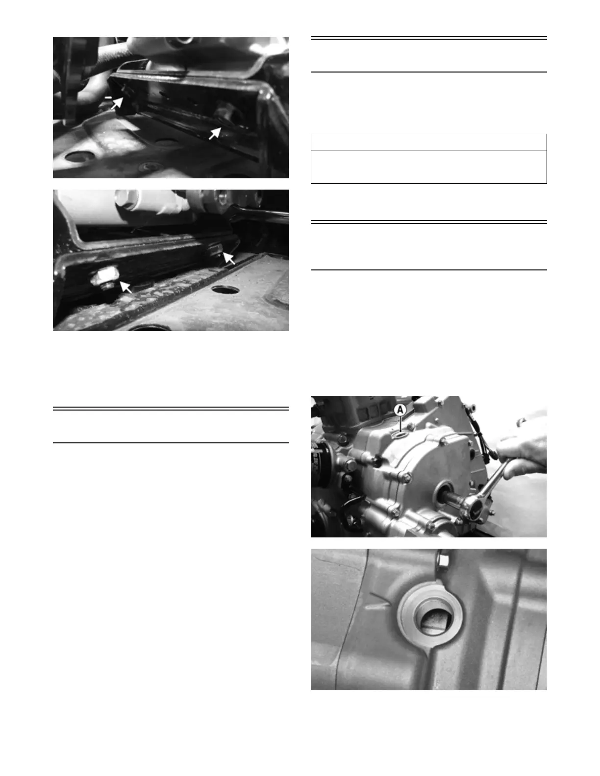
NOTE: Remove the spark plug, timing inspection
plug (A), and outer magneto cover plug; then using an
appropriate socket and ratchet, rotate the crankshaft
counterclockwise to top-dead-center of the compres-
sion stroke. Align the “T” mark on the rotor to the
timing mark on the magneto cover.
FI605B
FI709
AT THIS POINT
To service any one specific component, only limited dis-
assembly of components may be necessary. Note the
AT THIS POINT information in each sub-section.