107
FUEL PUMP/FUEL LEVEL SENSOR
The fuel pump and fuel level sensor are only service-
able as assemblies.
Testing
1. Turn the ignition switch ON and listen for a momen-
tary “whirring” sound of the pump building pressure.
If the sound is heard (several seconds), no electrical
checks are necessary. Turn the ignition switch OFF.
2. Disconnect the fuel hose from the gas tank; then
install a suitable pressure gauge.
PK191
3. Reconnect the fuel pump electrical connector; then
turn the ignition switch to the ON position. The fuel
pressure should build until the pump shuts off. Pres-
sure should read 3.0 kg-cm
2
(43 psi).
4. If the pump is not running, disconnect the fuel pump/
sensor connector.
5. Connect a multimeter to the power supply leads with
the red tester lead to the orange/red wire and the
black tester lead to the black wire; then turn the igni-
tion switch to the ON position. The meter should
read battery voltage. If battery voltage is indicated
and the fuel pump does not run, replace the pump
assembly. If no battery voltage is indicated, check
the ECM and the vehicle tilt sensor.
Removing
1. Remove the key from the ignition switch.
2. Remove the seat and access panel located at the bot-
tom of the passenger side storage tray; then discon-
nect the negative cable from the battery.
3. Disconnect the electrical plug from the main harness;
then disconnect the fuel hose connector from the fuel
pump.
4. Mark the fuel pump mounting and gas tank for
installing purposes; then remove the screws securing
the fuel pump to the gas tank and remove the fuel
pump. Account for the seal.
5. Using duct tape or other suitable means, cover the
fuel pump opening.
Inspecting
1. Inspect the fuel screen and blow clean with low pres-
sure compressed air.
2. Move the float lever and check for free movement.
The float assembly should return to the lower posi-
tion without force.
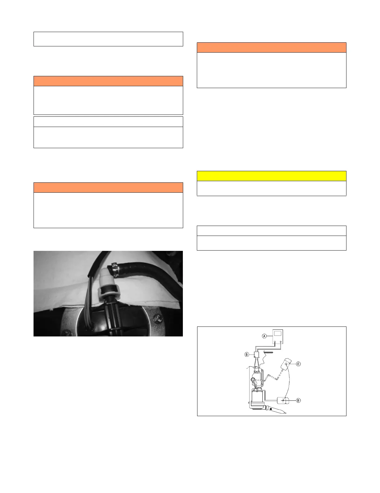
3. Test the fuel level sensor by connecting a multimeter (A)
to the fuel level sensor leads (B); then select OHMS. The
multimeter should show 101 ohms at full fuel position
(C) and 3 ohms at empty fuel position (D).
ATV2116
NOTE: If readings are erratic, clean the resistor
wiper and resistor with clean alcohol and retest. If
still not correct, replacement of the fuel pump level
sensor may be necessary.
Component data can be retrieved using the Dealer Diag-
nostic Service. Utilize the Sensor Data screen.
! WARNING
Whenever any maintenance or inspection is made on
the fuel system during which there may be fuel leakage,
there should be no welding, smoking, open flames, etc.,
in the area.
AT THIS POINT
Prior to removing the electric fuel pump, the following
check should be performed to determine that removal is
necessary.
! WARNING
Gasoline may be under pressure. Depressurize the fuel
system by disconnecting the fuel pump electrical con-
nector and running the engine until it stalls. Place an
absorbent towel around the connector to absorb any
gasoline when disconnecting.
! WARNING
Always ensure that power cannot be inadvertently
applied to the ignition/ECM when working on the fuel
system. If the ignition switch is turned on, the electric
fuel pump will start and gas could be rapidly pumped
and spilled resulting in fire and severe injury.
CAUTION
Take care not to damage the float or float arm or
replacement of the entire assembly will be necessary.
AT THIS POINT
If the pump has failed earlier test and must be replaced,
proceed to INSTALLING.
 Loading...